OK, a few thoughts. I hadn't considered David's point about the short interuption caused when throwing the toggle being seen the same as dirty track and perhaps resetting a sound system. I have never used a toggle in that manner and it semed like it should work, but he has a point.
I hope you have better luck with the MRC reversers than I did, they worked ok most of teh time with diesels but often failed to switch polarity, resulting in a breaker trip, when I ran steam. I believe this was due to the pilot wheels not picking up power as all (newer) diesel wheels do. I got the same short when I closed the gap between the main block and the reverse block with a jumper wire. I gave mine away and replaced tehm with Tony's , which have been flawless.
I don't think a center off would have changed anything for the fellow whose loco stopped when polarity changed. That's just odd, as others have said.
You can certainly wire both a dc pack and your dcc to toggles and throw it to either, just don't cross a gap from one to the other by mistake.
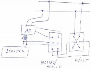
The auto reversers don't work with analog locos. I wired two of my reverse loops as shown in the (very) crude sketch below. AR is for auto reverser. The two toggles are marked "digital/analog" and in/out. This is not for running dc, it is simply to allow an analog loco running on dcc to use the reverse block. I built it to allow visitors locos to run on the entire layout. It hasn't been used in years! I leave the first switch in digital, and never have to worry about using either of them unless I run an analog loco. When I want to do that, I switch the first toggle to analog, and the other to in (I only run in one direction but if you want to run in both, perhaps label them east/west) After the train is in the block, stop it, flip the toggle to out, and change direction on the throttle. Now you are ready to depart. My reverse loops are staging at either end of the layout, so all trains sit for a spell anyway so this doesn't bother me.
I hope you have better luck with the MRC reversers than I did, they worked ok most of teh time with diesels but often failed to switch polarity, resulting in a breaker trip, when I ran steam. I believe this was due to the pilot wheels not picking up power as all (newer) diesel wheels do. I got the same short when I closed the gap between the main block and the reverse block with a jumper wire. I gave mine away and replaced tehm with Tony's , which have been flawless.
I don't think a center off would have changed anything for the fellow whose loco stopped when polarity changed. That's just odd, as others have said.
You can certainly wire both a dc pack and your dcc to toggles and throw it to either, just don't cross a gap from one to the other by mistake.
The auto reversers don't work with analog locos. I wired two of my reverse loops as shown in the (very) crude sketch below. AR is for auto reverser. The two toggles are marked "digital/analog" and in/out. This is not for running dc, it is simply to allow an analog loco running on dcc to use the reverse block. I built it to allow visitors locos to run on the entire layout. It hasn't been used in years! I leave the first switch in digital, and never have to worry about using either of them unless I run an analog loco. When I want to do that, I switch the first toggle to analog, and the other to in (I only run in one direction but if you want to run in both, perhaps label them east/west) After the train is in the block, stop it, flip the toggle to out, and change direction on the throttle. Now you are ready to depart. My reverse loops are staging at either end of the layout, so all trains sit for a spell anyway so this doesn't bother me.