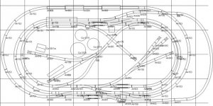
Best way to wire this layout

Connor

Member
Jan 25, 2005
116
0
16
48
Best way to wire this layout?

I've chosen this layout to build, but, there isn't any details on placement for power terminals and insulators, nor any info on how to wire the switches.

So, Here's what I'm looking for. I'm looking to wire this system for NON DCC operation with the ability to upgrade it in the future to DCC (without having to re-do my insulators and terminals).. Also, I would like to know, when it's appropriate to use a Snap-Relay with the Snap-Switches..

Note: Someone in this forum has built this layout as that's were I got the original from, but, I plan on making the scenery completely different including having a small river run through the layout. This layout is probably more than a newbie needs to start out with, but, I'm ambitious.
 

Attachments

  • Layout.jpg
    Layout.jpg
    65.3 KB · Views: 480

theBear

Member
Oct 1, 2004
185
0
16
In the woods of Maine
Connor,

The only thing you have to absolutely get right is that reversing loop on the inner most oval.

Other than that it becomes a question of how many trains do you wish to run at once?

Toss out that answer and someone might suggest a way of breaking the layout into blocks.

The breaking of a layout into blocks is exactly what I'm avoiding this time around.
 

Connor

Member
Jan 25, 2005
116
0
16
48
I'm looking to probably have 3 cabs + 1 more for the spurs and reversing loop.
Speaking of reversing loops, how does DCC deal with one?
 
F

Fred_M

Connor said:
Speaking of reversing loops, how does DCC deal with one?
You insulate both rails at each end of the loop and install a reversing module. Some use DPDT switches instead, but that risks sudden stops if the switch is improperly set upon entering or exiting the loop. Fred
 

theBear

Member
Oct 1, 2004
185
0
16
In the woods of Maine
Conner,

All two rail electric trains layouts have the same requirements when it comes to reversing loops since the outside rail becomes the inside rail and versa vice. It makes no difference if they are DC, DCC, or AC.

The loop creates a short circuit.

Fred is correct the traditional method is to use a dpdt switch to set the proper direction of entry for the loop and the same is true for the main. Swithes get flipped a lot doing it this way.

If you forget then when the train crosses the insulated gap you get a short and things come to a halt. Since the gap is at both ends of part of the loop you become restricted as to the length of train you can run. The train must completely fit inside of the area between the gaps or it is possible that the car wheels (if metal) will bridge the section and produce the short.

There are a number of devices to properly handle a reversing loop.

Three cabs+ will probably require some sort of plug/socket arangement as switches get expensive when the number of positions increase.

I'll look at the layout a bit later and let you know where I'd place the insulated gaps.
 

Connor

Member
Jan 25, 2005
116
0
16
48
theBear, Thanks... I guess the question about DCC with reversing loops is this.. I know the track must be insulated, I'm just wondering if the decoder board will relize a polarity change in the track and keep going it the right dorection.. (or does DCC have polarity, is it AC ??)
 

theBear

Member
Oct 1, 2004
185
0
16
In the woods of Maine
Connor said:
theBear, Thanks... I guess the question about DCC with reversing loops is this.. I know the track must be insulated, I'm just wondering if the decoder board will relize a polarity change in the track and keep going it the right dorection.. (or does DCC have polarity, is it AC ??)
The polarity the motor sees is what the decoder sends it, the decoder acts a rectifier here are some scope traces of the output of a DCC power pack http://www.wiringfordcc.com/dcc_waveforms.htm
 

Tad

Member
Apr 8, 2003
273
0
16
60
Boise, Idaho
Visit site
For DCC, they make reversing loop modules that are used instead of switches. If you want to use DC now, with DCC later, you could wire the reversing section with something such as an Atlas Controller. When you decide to go DCC, you would replace the Controller with a reversing module.

I wired my layout for DC operation with an eye towards future DCC conversion without having to rewire the layout. The way that I chose to do that was to fully isolate each turnout with insulated rail joiners. This also isolates each section of track between or beyond a turnout. I powered each turnout with a set of feeder wires soldered to the points end of the turnout. The isolated track sections between or beyond turnouts are all soldered together to become one electrical section. The insulated joiners provide for expansion joints. Each section has a set of feeder wires soldered to it.

I ran 14 gauge buss wires to the feeders and connected them with suitcase connectors. How the buss wires are connected to the feeders will determine how many blocks are in your layout. I wired all my blocks up through Atlas Selectors. If and when I decide to go DCC, all I would have to do is to disconnect a DC powerpack, connect a DCC command station in its place, and slide all selector switches one way and I would be set. I would also need reversing modules to contro my two wyes.

This is a way to do what you are talking about. It's how I chose to wire my layout. I'm sure there are different techniques.
 

Connor

Member
Jan 25, 2005
116
0
16
48
I'm not a little confused. If the DCC decoder acts as a rectifier, then I wouldn't think you would need a reversing loop modules, I thought those were for normal DC operation, not DCC. I was imagining just isolate both rails on the loop and would be good to go.
 

theBear

Member
Oct 1, 2004
185
0
16
In the woods of Maine
Connor said:
I'm not a little confused. If the DCC decoder acts as a rectifier, then I wouldn't think you would need a reversing loop modules, I thought those were for normal DC operation, not DCC. I was imagining just isolate both rails on the loop and would be good to go.
When the wheels bridge the gap you get a short unless both sections of the track are matched ... DC, AC, DCC makes no difference it isn't the the output of the decoder that matters.

The track is all about input to the engine, lighted cars, etc not the output.
 

theBear

Member
Oct 1, 2004
185
0
16
In the woods of Maine
Tad said:
.....

I wired my layout for DC operation with an eye towards future DCC conversion without having to rewire the layout. The way that I chose to do that was to fully isolate each turnout with insulated rail joiners. This also isolates each section of track between or beyond a turnout. I powered each turnout with a set of feeder wires soldered to the points end of the turnout. The isolated track sections between or beyond turnouts are all soldered together to become one electrical section. The insulated joiners provide for expansion joints. Each section has a set of feeder wires soldered to it.
That certainly leads to flexibility. I'd include the turnout in the block the point end was attached to.

You can bring each block's wiring out to a control panel with jacks so you can plug in the cabs. Bypassing all of those selector switches and making the number of cabs independent of the fixed wiring and allowing fairly easy conversion to DCC later.

There are many ways of handling the breakup.
 

Connor

Member
Jan 25, 2005
116
0
16
48
So the big issue is the wheels shorting out the track as it passes over the insulated joint. Geez, what a waste.. Having to use a special reversing module just to avoid something so simple as a mechanical short.
 

Connor

Member
Jan 25, 2005
116
0
16
48
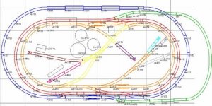
Here is another copy of my layout color coded with multiple lines. This is how I'm thinking of breaking it up..
 

Attachments

  • image0023.jpg
    image0023.jpg
    51 KB · Views: 360

theBear

Member
Oct 1, 2004
185
0
16
In the woods of Maine
Too many colors for my old eyes to handle.

Are those small blocks to be used as places to stop a loco? If so they could be connected to the adjacent block and a simple dpst or spst switch could be used to kill the power. I'm not saying they have to be done that way, just that they can.

I think you should have those ovals split a bit more. Basically the idea is to block at the switches, after you leave the frog end a new block starts.

What system did you use to render and color that layout? I'm still playing with design software and what I want for my layout. I have a basic idea and (too) many possibilities. Multiple fallen flags and still operating roads and a pile of interconecting junctions. I have a large if currently somewhat train unfriendly basement.
 

Connor

Member
Jan 25, 2005
116
0
16
48
I can render a higher quailty image that'll be easier to see, just couldn't upload it, too large. I'm using the Altas RTS software to render the color's, Took me a while to figure it all out.. I ended up have to disconnect all my track color code it, then re-connect because it wanted to color the whole thing the same color otherwise. Yes, the spurs are to be used to stop loco's and that's why they're color coded, most likly feeding from the yellow line (reversing sectioin) or possible a number of differnt lines using some switch magic. I'm thinking this layout should have 4 cab controlls (3 for the main lines,1 for the switch-yard and reverse section) I'm using atlas track with non-powered frogs, so, I really don't understand whats needed at the switches. I figured breaking them up where I did was best..

Thanks
 

theBear

Member
Oct 1, 2004
185
0
16
In the woods of Maine
I have a copy of the Atlas stuff sitting on a backup DVD but currently lack a system to run it on. Windows has been banished here
biggrin.gif
.

The size of the image isn't what causes me problems it is too many colors. They tend to distract me.

Basicly all I've ever done when it comes to blocking a layout is to follow a really simple rule that starts a block at the frog end of a turnout and to electricaly bond the point end. This rule is relaxed somewhat in yards by combining what would be very small blocks usually consisting of ladder turnouts. This means that there are four insulated joints at each turnout and they are all on the frog end. This is a simple method to follow. I've also added a couple of pockets on switches to allow parking of locos.

I haven't priced switches lately and shudder to think of the cost for a large number of cabs which is why I mentioned jacks & plugs instead of selector switches. There are all kinds of trade offs. The saving grace is that you can always add a block or combine adjacent blocks after you have tried the layout in an operational setting.
 

Connor

Member
Jan 25, 2005
116
0
16
48
I guess the switch stuff is what's confusing me.. I've been reading a Atlas book on how to wire stuff.. and in my layout, I've got the switches isolated on the frog side on the curve. The straight part of the turnout will be continuous. (I'll be using Atlas Snap-Switches and Turnouts which means no powered frogs)
 

theBear

Member
Oct 1, 2004
185
0
16
In the woods of Maine
Connor said:
I guess the switch stuff is what's confusing me.. I've been reading a Atlas book on how to wire stuff.. and in my layout, I've got the switches isolated on the frog side on the curve. The straight part of the turnout will be continuous. (I'll be using Atlas Snap-Switches and Turnouts which means no powered frogs)

Electrical type switches or track type (turnouts, points) switches (switch machines)?

Too many things called switches
biggrin.gif
.