

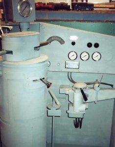
A couple of months ago I posted a picture of this model of an EMD
control stand after finishing the "drum" that holds one of my model railroad power packs. The throttle and reversing lever are operational as is the horn cord that activates a continuous loop tape of diesel horn sound. I've recently added a simulation of the independent brake valve. Pulling the handle to the right activates a can of compressed air hidden behind the instrument panel and makes a hissing sound. The bell switch to the right of the brake activates another loop tape of train bell sounds. This has been a fun project that lets me enjoy a sort of train simulator. Guests seem to like the interactive nature of the stand.
My question is about how to model the large automatic brake valve wih its cast metal seamless curves. I used sheet metal over a wood frame for the top of the throttle drum but am not sure how to create a smooth surface for the brake valve.
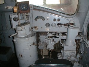
I'm including a picture for reference. Its from the cab of an actual F unit at the North Carolina Transportation Museum. They were kind enough to let me use the photo as a guide. The automatic brake is the large structure on the right side of the second photo.
Thanks for your ideas!
Ralph
control stand after finishing the "drum" that holds one of my model railroad power packs. The throttle and reversing lever are operational as is the horn cord that activates a continuous loop tape of diesel horn sound. I've recently added a simulation of the independent brake valve. Pulling the handle to the right activates a can of compressed air hidden behind the instrument panel and makes a hissing sound. The bell switch to the right of the brake activates another loop tape of train bell sounds. This has been a fun project that lets me enjoy a sort of train simulator. Guests seem to like the interactive nature of the stand.
My question is about how to model the large automatic brake valve wih its cast metal seamless curves. I used sheet metal over a wood frame for the top of the throttle drum but am not sure how to create a smooth surface for the brake valve.
I'm including a picture for reference. Its from the cab of an actual F unit at the North Carolina Transportation Museum. They were kind enough to let me use the photo as a guide. The automatic brake is the large structure on the right side of the second photo.
Thanks for your ideas!
Ralph
")