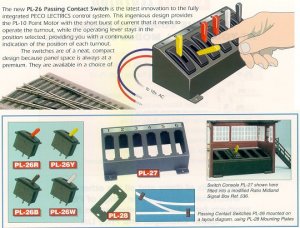
Turnout Switches

jland31

New Member
Apr 12, 2002
36
0
6
92
Ocala, Fl.
Visit site
Hi Folks;
Need some help pls.
I have 14 Peco turnouts with Peco PL-10 Motors.
Have been told that the Peco PL-26 momentary switches shud be used to power the PL-10's. Reason is that these switches are of high quality, won't burn out the PL-10's & show the direction on the control panel.
Has anyone had experience with the PL-26's?
Can you guys recommend other switches tha are better?
 

Woodie

Active Member
Mar 23, 2001
2,093
0
36
Northern Rivers NSW Australia
I use the PL-26 turnout switch, with no hassles, except mounting them. You need a reasonably accurate rectangular hole on a thin mounting. Just to be really safe etc, I intend to put a capacitor discharge unit in-line just in case. I've yet to make the CDU kit up.:cool:
 

jland31

New Member
Apr 12, 2002
36
0
6
92
Ocala, Fl.
Visit site
Wiring turnouts

Woody;
Thanx. Good to hear good things about the PL-26's. They're not the easiest thing to find making me feel they may be inferior in some way. I intend to mount them in the PL-28 mounting plates unless you have a better way to go.
Good idea using the capacitive discharge unit as backup. I have plans for one but see that Loys has one made up for about $7.00. Don't think I could buy the material for that. What do you think?
Thanx;
Jim
 

Woodie

Active Member
Mar 23, 2001
2,093
0
36
Northern Rivers NSW Australia
Yeah. I have the mounting plates as well. Not so much need for the accurate hole that way. I have no probs getting the switches or plates.

Yeah, I know you can get already made up CDU, but I thought I'd make my own up from a kit. (wasn't that much cheaper either).

A local electronics shop here stock about 50 different hobby electonics kit for model railways, ranging from deisel sound generators for locos, to flashing crossing light and auto control mechanisms to crossing boom motors, auto signalling etc.
 

60103

Pooh Bah
Mar 25, 2002
4,754
0
36
Brampton, Ontario, Canada
Visit site
Woodie:
are the PL26 the ones that make up to look like signal box levers?

Do they make contact with both parts of the switch machine when you throw them or do you have to push extra to get contact? I'm a little worried about the Capacitor unit as (if it's the first way) the capacitor won't have time to recharge before it tries to throw the points the way you want.

I use the Peco probe and studs, myself.
 

bobrien

Member
Feb 15, 2002
128
0
16
74
Waiuku,New Zealand
Visit site
I've just come from talking to my local hobby shop about the PL-26's and he was dead against again, preferring to use a button instead of a switch.
His concern is that the switches can burnt out motors if held down too long (who'd do that?) and told me that most modellers he knew much preferred a button action.
Any comments guys?
Bruce:confused:
 

kettlestack

Member
Jan 18, 2002
859
0
16
84
Scotland UK
Visit site
More Info

Welcome Jland,

Don't know if you have seen the PL-26's but for other members info I've attached a pic of them. They are passing contacts as they are swung to their direction resting position. 60103's comments are valid. Generally, Peco makes quality products but don't assume they (or any other highly regarded manufacturer) produce the Rolls Royce of the stuff within their field.
Personally, I use quality pushbuttons. Radio Shack #275-1547 is the type I use in conjunction with a Transistorised Capacitor Discharge Unit. These pushbuttons are currently listed @ US$2.99 but I'm sure they are available from other sources at lower prices. They require a 1/4" dia mounting hole so are easy to install.

Shamus uses an even simpler and less expensive (but efficient) method which is preferred by many modellers and is certainly worth considering. He shows his splendid control panel in his post within the "Photography" threads.

Just my 1.42 cents worth.

Errol
 

Attachments

  • peco switches.jpg
    peco switches.jpg
    75.6 KB · Views: 229

shamus

Registered Member
Dec 17, 2000
3,489
0
36
87
UK
I find the best way is to use stud and contact along with a capacitor discharge unit running off 24v ac, won't burnout any motors and you can make the panel easy using this method.To make the control panel I use two pieces of Perspex the right size for my panel. Next thing to do is draw out the plan on a computer programme to A4 size. When finished I print one copy on plain paper and another on Photo paper at top quality to use as the finished product.
The first piece of plain paper is used only to provide the places to drill the holes through for the D.P.D.T switches. Mine are 1/4" holes for my switches. (Micro switches) and also where to drill the holes for point control. 
When all drilling is completed, I remove the plain paper and clean up the two pieces of Perspex. Now I insert the new Photo Paper printout and I have a professional looking control panel just waiting to be wired up.
For my point control I use the stud and contact method utilizing a capacitor discharge unit, which has a 24 volt output for my PL10 point motors which I use to throw the points. The reason I prefer stud and contact over momentary switches (To throw the points) is I only need two tiny nuts and bolts (Brass) fitted to each point on the control panel. 
Here is what my control panel looks like, notice the nuts and bolts, these are my stud and probe contact for changing point direction. You will also notice that I have two switches per block, the reason, I could only buy D.P.D.T without centre off, so I had to put in beside the D.P.D.T.'s a separate on/off switch.
panel.jpg


jland31

New Member
Apr 12, 2002
36
0
6
92
Ocala, Fl.
Visit site
To Woodie = P-26's & Cap. Dis. Unit

Hey Woodie:
I'd sure like to have the name & address of your local shop that makes model R/R elect. kits. A thought though, do you folks "down under" use the same house voltage as we in the US use? [110/120]
How did your capacitive discharge unit kit go together & how does it work with the P-26's

Vacuum Tubes? Antone need some new in box 6AU6's or 12AU7's?
 

Woodie

Active Member
Mar 23, 2001
2,093
0
36
Northern Rivers NSW Australia
electronics kits

The store is Dick Smith Electronics
click here and type "model railways" in the seach box will give you the two books.
Have a look at "product categories" "kits" "model railways" for a couple of the kits.

The publisher of the kit books and manufacturer of the full array of kits is:
Talking Electronics Pty Ltd
click here

with the kits click here
I can highly recommend the two books. The websites don't have much detail or description, so if you wanna know anything, let me know.

All prices are in $Australian ($AUS/2 = $US)

The two books describe each kit in detail, circuit diagrams, and hints for usage.
 

Woodie

Active Member
Mar 23, 2001
2,093
0
36
Northern Rivers NSW Australia
jland31,
We use 240V down here, but the kits are independant, as they use the voltage from your controller.
The CDU unit does the same. I run it from 17V AC output on my controller.

BTW..... my control panel! (as it was). my "switch" was just the other wire!! A few sparks fly when you "connect" the "momentary" wire, but it worked fine!
 

Attachments

  • maybuild04.jpg
    maybuild04.jpg
    14.6 KB · Views: 200

bobrien

Member
Feb 15, 2002
128
0
16
74
Waiuku,New Zealand
Visit site
Woody

Did you say somewhere that you used the Peco motors with the extended pin only (PL-10E), or did I imagine that?
If you did, did you use it exclusively (that is for all your turnouts) or just some?
My thoughts were that the worry over using anything electrically operated with more moving parts than necessary (eg, the extended pin) could lead to later problems - was offset by the better thought (in my opinion) that by mounting the motors under the baseboard (as in the 10E), access in the event of a burnout would be much easier.
I would appreciate any comments before I finally decide which motor to install :)
Cheers
Bruce
 

Woodie

Active Member
Mar 23, 2001
2,093
0
36
Northern Rivers NSW Australia
extended pin

Bruce,

I used both. If the track is laid straight on the baseboard, then I have mounted the turnout motor 
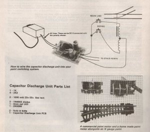
under the baseboard, with the extended pin. (had to cut a bit off, but that's OK). If the track is on elevated on risers, then I used the turnout motor mounted directly on the turnout with the lugs and holes. Doing it this way, of course, mounts the motor better and more accurate than a "guess" where to drill the mounting holes, but also burys it under the track, without access, unless I rip the track/ballast/risers up. I suppose I could drill a 15cm hole under the spot, through the baseboard, so I can get my clumsy fingers up there, incase of a burnout, but that is the risk I took. I've not had a burnout yet. They seem pretty robust. even 5 - 7 secs of continous 17V AC (done accidentally) didn't do any damage to them.

When mounting under the baseboard, ensure you mount them corectly, with the turnout rails held "centrally" so the pin can be mounted "centrally" with the motor as well. Pretty tricky at first, but you'll get the hang of it. :cool: Ensuring the turnout is "perpendicular" to the track is a bit tricky too, when mounting under the baseboard, as you have no point of reference as to the exact direction of the track, so you can mount the motor appropriately. Be sure to drill the hole through the baseboard before fixing the turnout down. I used a 1/2" hole to allow enough movement of the pin from side to side. Be carefull when ballasting you turnouts too. The ballast can go down the hole and jam in the turnout motor. I have now learned to place a piece of thin paper between the turnout and baseboard/motor before fixing them down. The motor will then make just enough of a hole for itself (when switched). The hole it makes is not big enough for ballast to fall down into the turnout motor.

The "throw" of the turnout motor is more than is needed to "throw" the turnout, and because of the "swivel" of the motor pin, it does allow a bit of flexibility/inaccuracy when mounting under the baseboard, but the more accurate the better. I have a couple of turnouts (with underboard motors) that give a great thump in one direction (so much so, that they "bounce back" sometimes), and only just enough "throw" in the other direction, because of "inaccurate" mounting.

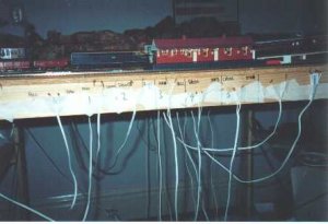
BTW. I can only get enough current out of my controller (17V AC 1.6 AMPS) to throw no more than 3 turnouts at once. Anymore, and there's not enough current to throw the turnout motors. I have a double crossover on my layout (using 4 turnouts and a diamond crossing) and wanted "straight through" or "crossover" mode on the flick of a single switch. I've had to settle for two switches with 2 of the turnouts on each.

Those 4 turnout motors are buried under the risers, so even if one of them blows, I've gotta rip the whole lot up. 4 ballasted and stuck down turnouts could be expensive to replace, should even one of the motors blow!!!
 

bobrien

Member
Feb 15, 2002
128
0
16
74
Waiuku,New Zealand
Visit site
Thanx Woodie - a great help. Luckily I will have only one elevated turnout (which I just bet will be the bugger to burnout one day...) and the rest either on the baseboard or close enough not to be a problem.
I had already figured that the need for current to throw more than 3 switches would be a problem, but I will probably take the same approach that you have and work around it. But all the same, thanks for the tips, because you have already been down the road I am about to travel and i sure do appreciate the help.

BTW - good luck to the Waratahs tonight. The whole of NZ is just counting on them beating the Brumbies so we can have a rematch of last week :D :D :D :D

Bruce
 

bobrien

Member
Feb 15, 2002
128
0
16
74
Waiuku,New Zealand
Visit site
Woodie - is that a gap I can see around your crossover? It looks like you can see the cutout but it may be my imagination....

I was given the advice of using heavy grade masking tape around the drill holes or cutouts to take loose ballast. Anything I guess to keep the stuff from fouling the motors.

Bruce
 

Woodie

Active Member
Mar 23, 2001
2,093
0
36
Northern Rivers NSW Australia
Waratahs? Who are they?? :eek: :eek: Rugby thugby mugme bugme lugme...... That's not footy!
Swannies play Essendon at the Olympic Stadium next Sat. (first AFL game to be played there). Expecting a bigger crowd than the State of Origin (which is next Wed).

Oh... BTW.... the gap (line) you see between the tracks is the gap in the elevated roadbeds (I used balsawood roadbed). I've filled it in now.
Masking tape would do just as well as the paper, but keep it as thin as possible, otherwise you'll get bumps and derailments on the turnouts. :mad:

That's why I've always said Garahbara MK I has always been earmarked to be thrown away. Learing curve it is. And, boy, have I learnt! :p
 

bobrien

Member
Feb 15, 2002
128
0
16
74
Waiuku,New Zealand
Visit site
Throw it away?? Now I know that's REAL railway modeller talk, but holy hannah Woodie, I just couldn't do that. All that hard work. All those hours plannning those intricate little details...
Nah - pack it up and put it somewhere you can drag it out now and then to say to yourself "well that was fun, but boy, look at it compared to my new bigger brighter actually working properly one!"

And back in 1983, I actually was introduced to some of the Swans team (of that year of course) at the Supporters Club somwhere in the bowels of some part of Sydney and was told that as a Blues supporter, I had to shout the bar - which I managed to get out . Of course.
Nice guys, if a little tall ;)

Bruce