St. Louis Terminal layout plan

CarlFidy

New Member
Jun 17, 2002
88
0
6
53
Owasso, OK
Visit site
This is an idea I've been toying with for about 9 months.

For those not familiar with the St. Louis area, they have the Terminal Railroad Association of St. Louis(TRRA). This company is owned by many of the other railroads that serve the area - kind of a "shared assests area". They own all three rail bridges across the Mississippi River at St. Louis, plus associated approach trackage and many yards for consolidating and transferring freight between member railroads. When it was in service they also owned Union Station.

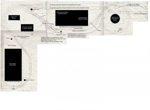
From the west (the helix), the track plan depicts an area beginning at Grand Ave. Tower. At this tower BNSF(ex BN, ex SLSF), UP(ex MP), NS(ex N&W, ex Wabash - Rock Island used this track to get to Union Station) converge into the Mill Creek Valley which is the primary rail corridor down the river and the bridges. The TRRA's Merchant district also starts at Grand Ave. Tower. This is the route all passenger trains from the west took to get to Union Station.

Continuing past Grand Ave. Tower, you pass Tower 2 and on to Tower 1 which controlled the approaches and throat of Union Station(42 platform tracks served by two triple-track wyes!!!). Beyond the station, you approach Gratiot Tower. Here trains have three choices: 1) go across the MacArthur Bridge 2)go north on the High Line (in front of the Arch) to the Merchants Bridge or 3) UP trains can go south on the High Line to Lesperance Yard.

Most of the trains on this route would be through freights, transfer jobs between the many yards in the area, and passenger trains which all stop at Union Station. No switching along the main line.

All switching activities would be in the Manufacturers Railway area. In real life Manufacturers is owned by Anheuser-Busch and they of course serve the brewery plus many other industries in the immediate area. Can't ask for a better combination - trains and beer.:D :D

Please let me know what you think of this concept/plan. All feedback welcome.
 

CarlFidy

New Member
Jun 17, 2002
88
0
6
53
Owasso, OK
Visit site
oooops!!!

Forgot to include the track plan...

Grid is 2" per square. Plan is 8'4" down left side and 12'8" along top to the far side of the helix.

Also, please let me know how the plan loads on your computers - first time I've attached something to a post.
 

Attachments

  • track plan 5.jpg
    track plan 5.jpg
    89.4 KB · Views: 514

Tyson Rayles

Active Member
Sep 25, 2001
4,310
0
36
Poverty Acres, North Carolina
Visit site
Hey Carl, I think Jim Seneese (hope I spelled that right) and Chuck Hitchcock are doing something along this line that MR did some write-ups on a while back. It's a interesting concept, sorta like a gaint time saver layout that lends itself well to massive urban scenery. Ought to be a lot of fun in the modeling and operation areas both. Gonna be alot of switches and track to clean and maintain though! :eek: You didn't say what scale (or I missed it if you did), I'm guessing N-Scale???? On your other post about computer programs MR did a article comparing the different ones a while back, but don't remember which ranked higher as that's not somethig I'm into but maybe somebody else here knows. Keep us posted on progress, it should be alot fun watching this puppy come to life! :cool: P.S. The drawing came thru fine on this end!
 

YakkoWarner

Member
Mar 10, 2001
291
0
16
55
Orange County, NC.
www.the-gauge.com
That's a great plan, well compressed and offering an incredible amount of modeling, switching and running operations. I hope you do undertake that so I can see the finished product.

One area that may give you trouble is the corner. At some point you will need to access it and it looks to be quite a stretch from the edge of your benchwork to the back there. (over the space reserved for the laptop.)
 

CarlFidy

New Member
Jun 17, 2002
88
0
6
53
Owasso, OK
Visit site
Originally posted by Tyson Rayles
I think Jim Seneese (hope I spelled that right) and Chuck Hitchcock are doing something along this line ... You didn't say what scale ... The drawing came thru fine on this end!

I've heard of Jim's layout and am hoping the get a chance to see it in the futrure...If I remember right, he's not to far from me. If anyone knows what issue of MR the right up is in I would appreciate the info.

N-Scale, definately!!

Was concerned about the drawing because it took me 5:mad: tries to get it attached. Had to keep shrinking it to make file small enough.;)

Yakko, just checked on your concern. If you can see on the plan, there are 3 sections to the "benchwork". 1) the corner - 4'x4' with one corner cut off 2) the wing under Union Station - 2'x4' 3) the wing under Manufacturers Railway - 2'x8'. These 3 sections of "benchwork" already exist in that I've built a temporary table to those dimensions. Actually typing this with the laptop in it "reserved" spot. Since table height (the level the laptop sits at) is going to be about 27" and there won't be any detailed scenery at the front edge, I can lean on the edge and reach the corner.

Thanks for the quick replies Tyson and Yakko. Looking forward to yours and others continuing input as I refine the plan.
 

Tyson Rayles

Active Member
Sep 25, 2001
4,310
0
36
Poverty Acres, North Carolina
Visit site
First off Jim Senese I'm sorry I misspelled your name in a earlier post here. Carl those articles are in MR's sister publication Model Railroad Planning. The 1999 issue has Jim's starting on page 18. The 2002 issue has Chuck's starting on page 68. If you don't have or can't get them let me know and I'll see what I can do about getting photo copys to you if you want. :)
 

CarlFidy

New Member
Jun 17, 2002
88
0
6
53
Owasso, OK
Visit site
Tracks entering helix

David,

The tracks shown on the plan enter the helix on three different levels. The three tracks in front of the switching area enter the first level. From Gratiot tower, the High Line approach goes down grade to enter on the second level, while the MacArthur approach continues up grade to the third level. The helix will then lead down to staging tracks/levels below the layout. Something similar to what Rich Weyland did for his N&W Pocahontas Division(shown in MR Model Railroad Planning 2002 - page 76, see specifically sidebar on page 80). Before seeing the article,I had already thought of the multil-level staging but it was very exciting to see someone successfully using the idea.
 

MikeB

New Member
Jun 29, 2002
2
0
1
57
Visit site
I just found this forum and was working my way down the boards, what do I find? The idea I have been toying with for the past few months already under construction!

I live in St. Louis and have also been considering modeling the terminal, I'll have to fine copies of the magazines mentioned and look at the work of other people.

Good luck on your project Carl!
 

shamus

Registered Member
Dec 17, 2000
3,489
0
36
87
UK
Hi MikeB, and welcome to the gauge.

Carl great looking trackplan, looks like you are about to start having some fun.

Shamus
 
LAPTOP??

Hi Carl, and welcome to the gauge. Sounds like a great plan for a layout, I will be anxious to see progress pics of it. Being a neubie at the hobby, I'm curious as to what the space for the laptop is for, is your power source DCC, and if so is the laptop able to control your layout?? You sure got my curiosity up. Thanx for the post. AT&SF Duey
 

CarlFidy

New Member
Jun 17, 2002
88
0
6
53
Owasso, OK
Visit site
More drawings/sketches on the way...

First let me add my welcome to MikeB. And Mike, don't let the fact that I'm working on a similar idea slow you down. What you decide to include as "must have scenes" of the area and the space you have to dedicate to a layout, would lead to a greatly different layout. So get out the drawing supplies and get to work!!!:) :) Only one requirement, now that you've joined the guage, you have to share your progress with the rest of us.;) ;)

Thanks, shamus. I deifinately admire your modelling and photographic work and skills. I have just barely scratched the surface of your website because I need to dedicate some time to looking at your it since my normal connect speed is only 26400!!!:mad: :mad:

AT&SF Duey - Thanks for the welcome. DCC is a must have for the operating plan I envision - too many trains too close together for block control. I'm wanting to use the laptop for some control aspects, but I need to do a little more research on the feasibilty, capabilites, and requirements for hardware and software. I think KAM Industries has some products for this purpose. If I can tear myself away from the gauge, I'll go check their site out.

Typical of a lot a peoples situation, the room for the layout needs to serve several purposes. Since I'm getting ready to go back to driving tractor trailers cross-country, I'm living with my parents - can't see the need to pay for an apartment I'll only use 4-5 days a month. So during my time at home, my room (12' x 15') will serve many uses - bedroom, home office, entertainment center, and of course layout room. So with these needs in a I'm trying to build a piece of "furniture" that will accomidate the layout, entertainment center, and computer/printer/scanner. Unfortuately, none of the furniture manufacturers make a product to fit all those needs.:( :rolleyes:

Like the subject line of this post says, I'm working on some more drawings and sketches to show ya'll how I think I can make all of this work together. Hope to have something to post tomorrow...
 

Drew1125

Active Member
Jan 28, 2001
2,975
0
36
Hi Carl!
This is just a thought...since I'm not real clear on what kind of scenic ideas you're planning...
Have you thought about incorporating some simple wall shelving into your "office" area, to support the RR? (or is there a problem with drilling in the walls for brackets?) Keep in mind that where you have a simple mainline run, scenery, & benchwork don't have to be excessively deep...12" - 18" would be plenty for such a situation.
This is also a personal opinion I hold (I'm sure there could be some disagreement here...) I think a layout is a lot easier to enjoy for all concerned, if the builder concentrates on making it an accent to a room, rather than an obstacle.