Manually Thrown Turn-outs

Gary S.

Senior Member
Oct 13, 2005
1,576
0
36
Texas
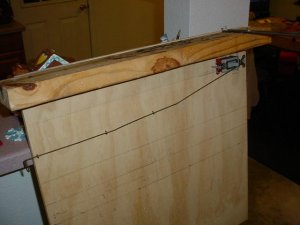
Would you throw a turn-out using a mechanism like this?

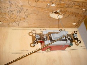
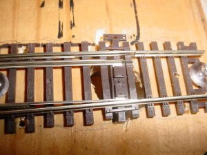
This is an experimental version. I used a coat hanger for the push-pull rod, an everyday type electrical light switch for the mechanism, and a piece of tie wire to connect up to the turn-out. Perhaps a piece of small diameter spring steel or brass rod would work even better.

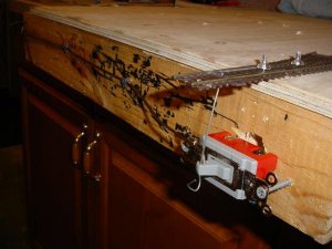
It actually operates fairly well. The push-rod would extend through the fascia and a cabinet drawer type knob could be epoxied on.

The switch contacts could be used for signals or indicators lights or something. Could be either a single pole single throw or a single pole double throw as needed.

What do yall think? oh... just so no one is confused by the pics... the side of the 2x4 represents the top of the layout and the turn-out is sitting on that, the piece of plywood is not the top of the benchwork, I was just using it to try out different angles of the pushrod, seeing just how far down I could go and still make the switch work.

P.S. I saw an idea similar to this on the internet and modified it using different stuff.
 

Attachments

  • manual throw overview.JPG
    manual throw overview.JPG
    30.2 KB · Views: 69
  • manual throw switch.JPG
    manual throw switch.JPG
    41.9 KB · Views: 71
  • manual throw track.JPG
    manual throw track.JPG
    43.8 KB · Views: 70

Pitchwife

Dreamer
Apr 23, 2001
1,728
0
36
71
The middle of nowhere Oregon
Visit site
I'd say that as long as it held the points solidly in either direction it should work fine. Using the contacts to control indicators would be a must or you could have some unfortunate mishaps. The only draawback I see is that you'ld have to have something verticle under the benchwork to mount the switch on so that it would be oriented corectly.
I was planning on using something along this line for my turnout controls. I found a place where you can get spring loaded solinoids for $1.50. Connect a spring wire to the piston to run up to the points and use a DPDT switch to activate it, one side for the relay and the other to turn on an indicator. I just have a problem paying $15 for a Tortois switch or taking a chance on burning out a pulse switch by applying the power too long. These are much more forgiving.
 

Gary S.

Senior Member
Oct 13, 2005
1,576
0
36
Texas
Where did you find the $1.50 solenoids? I may want to give that a shot too.

The electrical switch has 1/2 inch of travel from one position to the other. The turnout has 1/8 to 3/32 of movement. The tie wire acts like a spring and puts pretty good pressure on the turn-out slider mechanism... maybe too much. This could be adjusted by drilling the hole in the toggle handle closer to the switch body.

This setup seems pretty promising and straightforward for ease of building.
 

Gary S.

Senior Member
Oct 13, 2005
1,576
0
36
Texas
here is another photo. I rebuilt it so it would be more obvious. I think just an extra piece of 1xwhatever board attached to the benchwork as a crossmember would work great.
 

Attachments

  • manual turnout rebuilt.JPG
    manual turnout rebuilt.JPG
    38.1 KB · Views: 67

Pitchwife

Dreamer
Apr 23, 2001
1,728
0
36
71
The middle of nowhere Oregon
Visit site
Gary S. said:
Where did you find the $1.50 solenoids? I may want to give that a shot too.
I got them from All Electronics Solinoids They are rated at 24 volts intermittent but will work with 12 volts. I figure that will give me a longer active period. At 1/2 their rated voltage, they should stay active long enough to run anything but a super long train through them. In the OFF position they will be set for through traffic and only be on during the actual switching procedure. The throw is a couple of inches, but can be shortened with with the mounting screw. The nice thing is they can be mounted directly to the underside of the layout base unless you are using only foam. Then they will need a solid board to be mounted on.
I just looked and they have smaller 3-6V relays for $1.35, but they are intermitant and I don't know what the duty cycle is for them. With the larger solinoids at 1/2 their rated voltage, they should stay active longer. I was thinking of a setup similar to yours with the relays connected to the points by a stiff wire and all of the relays for that area mounted in a row. That way they can be accessed easily and controled through a pannel from a convienient location.
 

Gary S.

Senior Member
Oct 13, 2005
1,576
0
36
Texas
Thanks for that link. Those solenoids open up all kinds of possibilities. Now, the 10% duty cycle is a concern... here is something I dug up:

[font=Arial,Helvetica,Geneva,Swiss,SunSans-Regular]A typical solenoid requires 10% of the normal current to remain energized. To accomplish this, use one of the following:[/font]


  • <LI class=MsoNormal style="mso-list: l1 level1 lfo7; tab-stops: list .5in">[font=Arial,Helvetica,Geneva,Swiss,SunSans-Regular]Mechanical hold in resistor[/font] <LI class=MsoNormal style="mso-list: l1 level1 lfo7; tab-stops: list .5in">[font=Arial,Helvetica,Geneva,Swiss,SunSans-Regular]Capacitor discharge and hold in resistor[/font] <LI class=MsoNormal style="mso-list: l1 level1 lfo7; tab-stops: list .5in">[font=Arial,Helvetica,Geneva,Swiss,SunSans-Regular]Transistorized hold in circuit[/font] <LI class=MsoNormal style="mso-list: l1 level1 lfo7; tab-stops: list .5in">[font=Arial,Helvetica,Geneva,Swiss,SunSans-Regular]Pulse-width modulation[/font] <LI class=MsoNormal style="mso-list: l1 level1 lfo7; tab-stops: list .5in">[font=Arial,Helvetica,Geneva,Swiss,SunSans-Regular]Pick and Hold [/font]<LI class=MsoNormal style="mso-list: l1 level1 lfo7; tab-stops: list .5in">[font=Arial,Helvetica,Geneva,Swiss,SunSans-Regular]Dual voltage[/font]
  • [font=Arial,Helvetica,Geneva,Swiss,SunSans-Regular]Multiple coils[/font]
So maybe the duty cycle could be increased with some additional components. Also, since what we are worried about is overheating the coil, I am thinking that the duty cycle would increase at an exponential rate as the voltage is lowered. (P = I^2xR) Perhaps 1/2 the voltage would give a 4 times greater duty cycle instead of just doubling it?
 

pgandw

Active Member
Jul 9, 2005
1,002
0
36
A similar arrangement using push-pull rods of various descriptions, but substituting a slide switch for the light switch has been featured in some magazine articles. The slide switch is physically a lot smaller, and has the smaller throw you are looking for.

yours in switching
 

Pitchwife

Dreamer
Apr 23, 2001
1,728
0
36
71
The middle of nowhere Oregon
Visit site
Gary S. said:
So maybe the duty cycle could be increased with some additional components. Also, since what we are worried about is overheating the coil, I am thinking that the duty cycle would increase at an exponential rate as the voltage is lowered. (P = I^2xR) Perhaps 1/2 the voltage would give a 4 times greater duty cycle instead of just doubling it?
That's what I am figuring on. It's got a pull force, 3.7 lbs @ 24 Vdc. A set of points doesn't need anywhere near that, so I am figuring on determining the lowest voltage required to activate the solonoide, presumably 12V. That should put the duty cycle at a useable figure. The thing to remember is that at half the voltage it will pull twice the current so a heavier power supply is in order. A continuous duty cycle would be ideal, but so far I haven't found anything like that in the price range. These are pretty heavy duty. I guess the only way to tell for sure is to hook it to 12V and a timer and run it till it fries. :eek: :p At $1.50 it's not an unreasonable experiment. :)
pgandw said:
A similar arrangement using push-pull rods of various descriptions, but substituting a slide switch for the light switch has been featured in some magazine articles. The slide switch is physically a lot smaller, and has the smaller throw you are looking for.
yours in switching
The difference with a slide switch and these are that these are spring loaded which would guarntee a positive pressure on the points in both directions. An ordinary slide switch would allow a set of points set halfway from one position to the other. A sure reciepe for disaster. Seems I've seen a mechanism to spring load something like that, but this way it is already built in.
 

MasonJar

It's not rocket surgery
Oct 31, 2002
5,362
0
36
Ottawa, Canada
Visit site
You can "effectively" spring load the slide switch by putting a "Z" bend in your coathanger wire. Size/place it so it will be under compression when throw away from you, and under tension when pulled towards you.

Andrew
 

Gary S.

Senior Member
Oct 13, 2005
1,576
0
36
Texas
Pitchwife said:
The thing to remember is that at half the voltage it will pull twice the current so a heavier power supply is in order

My thinking is that since we are using DC for this coil, and the coil has a fixed resistance, reducing the voltage from 24v to 12v will have a corresponding reduction in current. Lower the voltage, lower the current, based on Ohms Law of I = E/R .
 

Gary S.

Senior Member
Oct 13, 2005
1,576
0
36
Texas
MasonJar said:
You can "effectively" spring load the slide switch by putting a "Z" bend in your coathanger wire. Size/place it so it will be under compression when throw away from you, and under tension when pulled towards you.

Andrew

The thing that appeals to me about the regular type light switch is the positive spring-loaded throw. Also the length of travel of the handle would give a nice positive feel at the knob at the fascia, and you could tell the position of the switch by looking at the position of the knob.

Now, if the travel is too much compared to the travel of the points, the hole for the attachment wire to the points can be drilled closer to the pivot point of the switch handle.
 

MasonJar

It's not rocket surgery
Oct 31, 2002
5,362
0
36
Ottawa, Canada
Visit site
I like the idea of the regular light switch too, and they may actually be cheaper...

But I just wanted to put up the idea of the Z-bend in case anyone else was reading and wanted to use the smaller slide switches.

Andrew
 

hminky

Member
Oct 13, 2004
396
0
16
76
I bought some slide switches from All Electronics that had a positive stop. The were 100 for $20.00 or $25.00.

Just a thought
Harold
 

Gary S.

Senior Member
Oct 13, 2005
1,576
0
36
Texas
$20 for 100 is cheap.

A SPDT (3-way) wall type light switch is going to run between $1.50 and $5.00 depending on the quality. A SPST will be somewhat less.