How does one turn printed panel lines into physical panel lines?

Rhaven Blaack

!!!THE MAN BEHIND THE CURTAIN!!!
Staff member
Administrator
Moderator
Jun 12, 2009
12,525
9,907
228
Oregon
www.deviantart.com
Hello Ladies and Gentlemen,

As many of you who know me, I am also a member of various "FB" model builder groups. One of the most common questions that I see being asked "How does one turn printed panel lines into physical panel lines?" The answer is both complicated and easy at the same time. First, let me address what panel lines truly are.
Panel lines are formed when one "panel" is attached to another "panel". Usually one panel overlays another just enough to put rivets in both, to connect them. Another way to connect two panels together is by welding the two together. More often than not, you get a "raised" surface (from either the edge of the overlayed or from the welding.) You can also rivet the paneles to an underlying piece of metal. This will result in a "depression/recess" being formed.

So, for this tutorial, I am only focusing on the recessed panel lines and how to make them physical. I am building the Colonial Viper from Sirious Replicas. Believe it or not, for being a relatively simple model template (only three pages of parts), there is quite a bit of greebling potential to have fun with (and practice how to greeble out a model, if you never have.).

(*NOTE* Not only am I planning to build this with recessed panel lines, but I am also going to build this with a shed load of greebling.)
v1.jpg

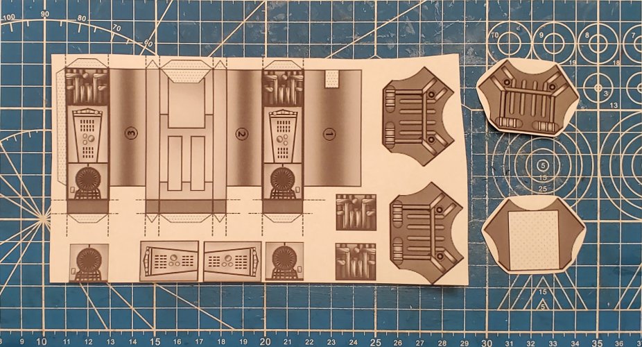
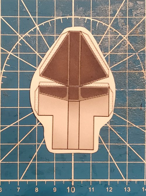
I have printed the template three times on cardstock and once on printer paper.
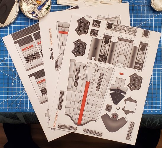
20231228_112030.jpg

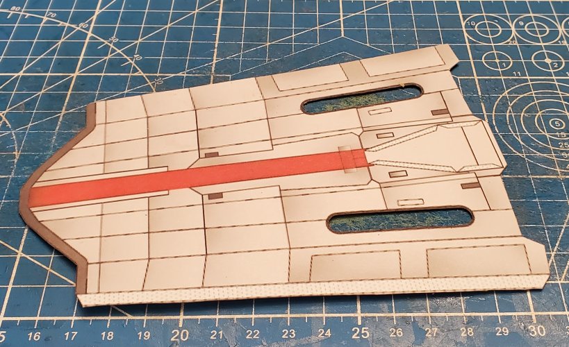
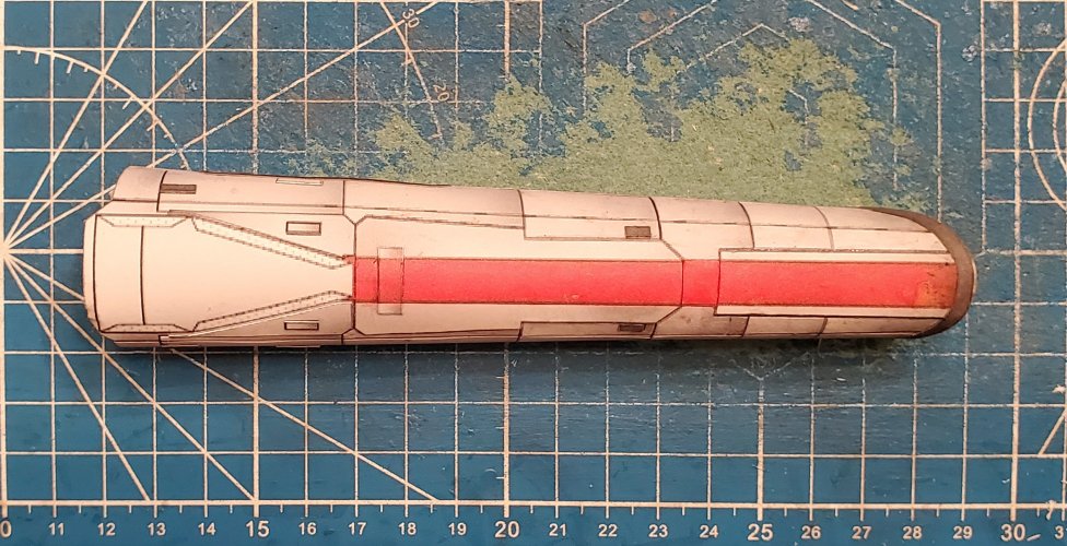
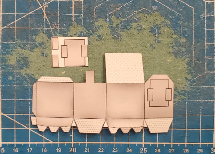
Starting with the fuselage. Here is the cardstock piece and the printer paper piece. When cutting the panels out, make certain that you are cutting away the "panel lines", so that the panels have no coloured edging from the lines.
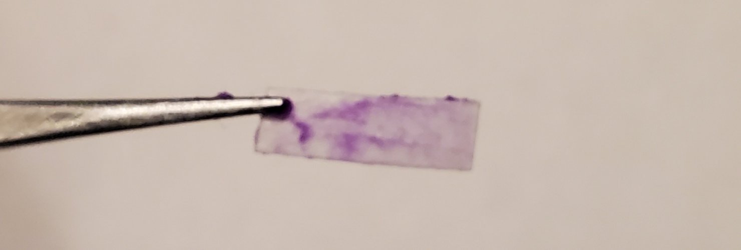
For laminating, I am using Elmer's "Purple" glue stick. (*NOTE* The glue does go on purple and dries clear.)
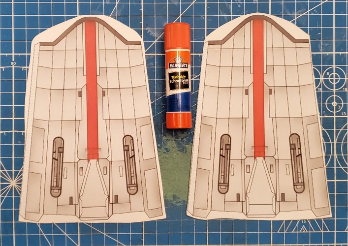
20231228_112549.jpg

Here is the first piece with the purple glue.
20231228_114107.jpg

I have started applying the panels.
20231228_131732.jpg

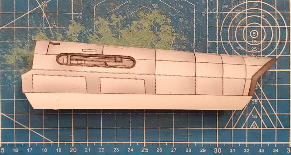
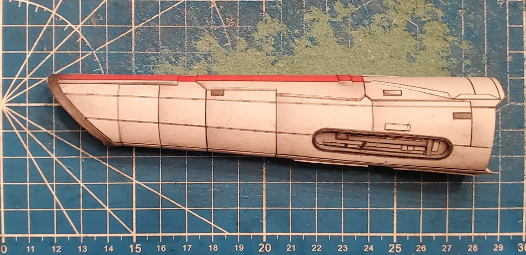
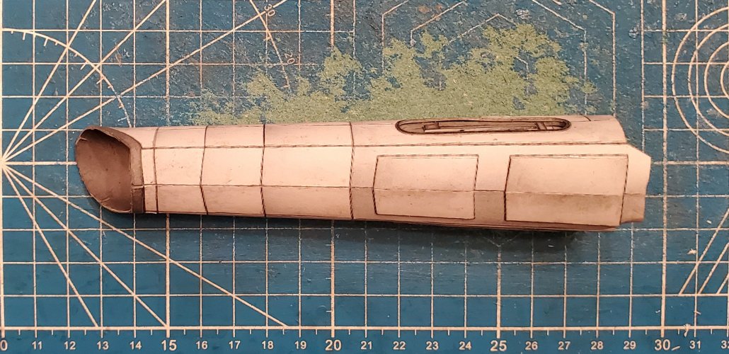
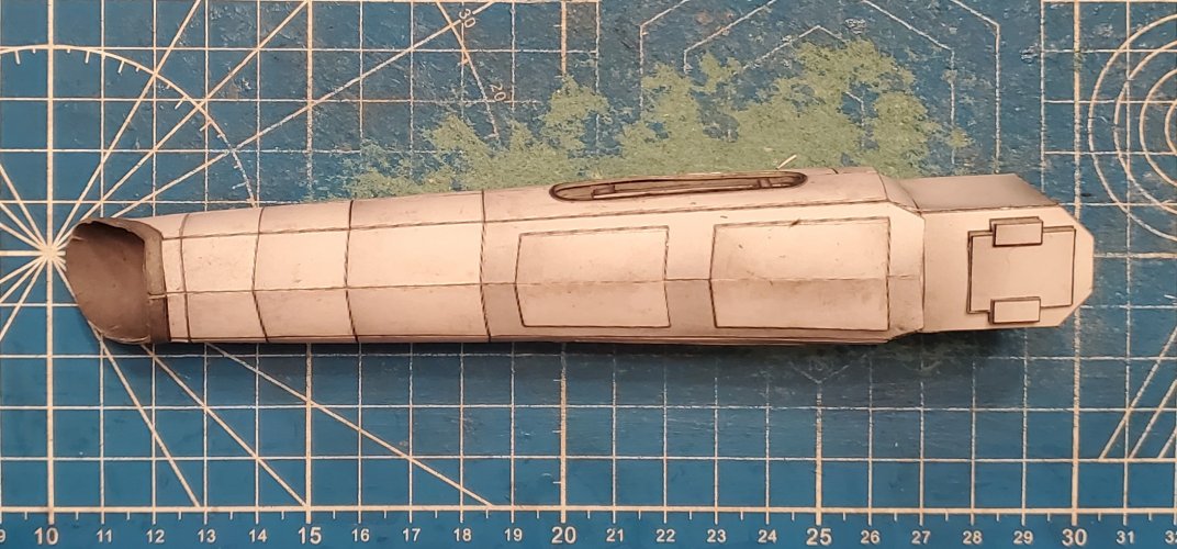
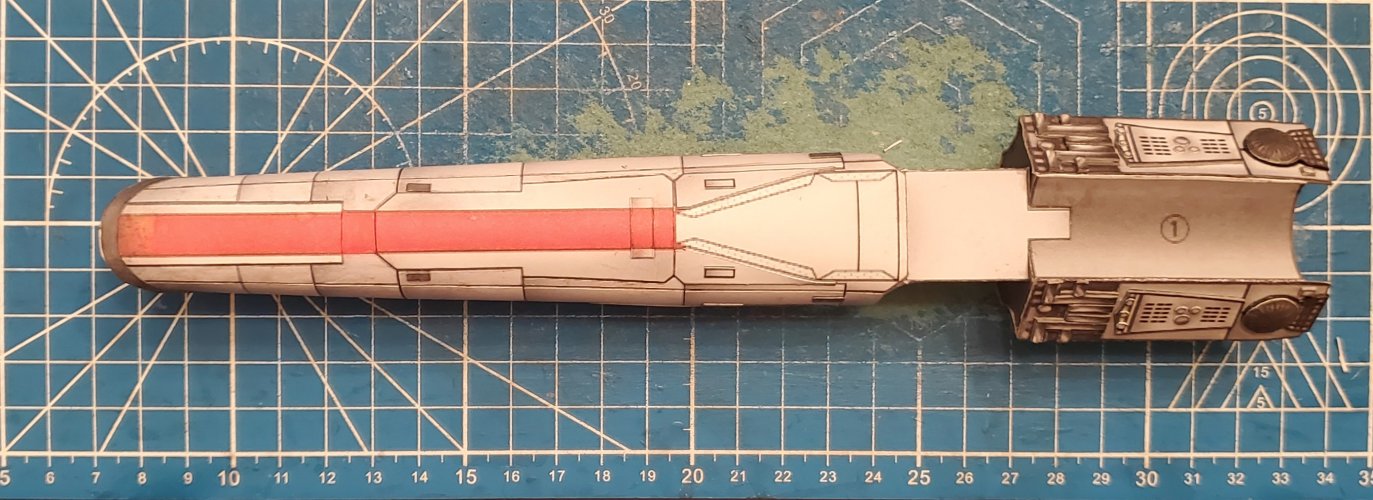
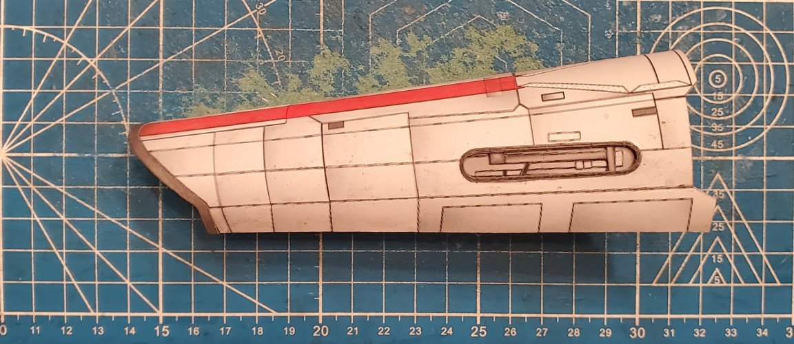
Once all of the panels have been applied, you can roll the fuselage and attach the recess panels.
20231228_230934.jpg

20231228_231016.jpg

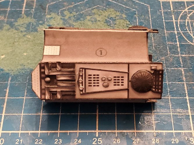
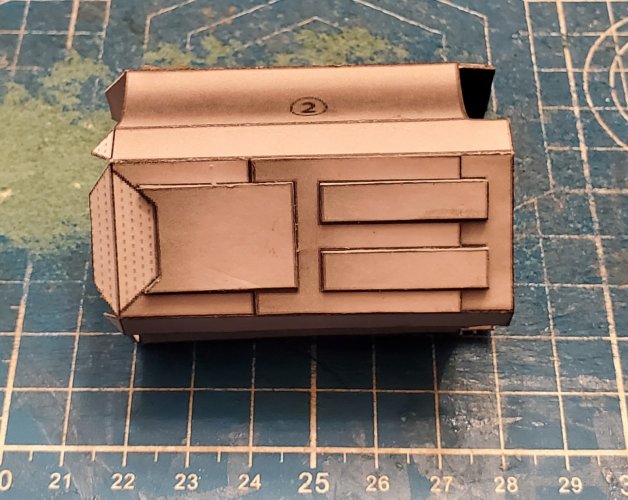
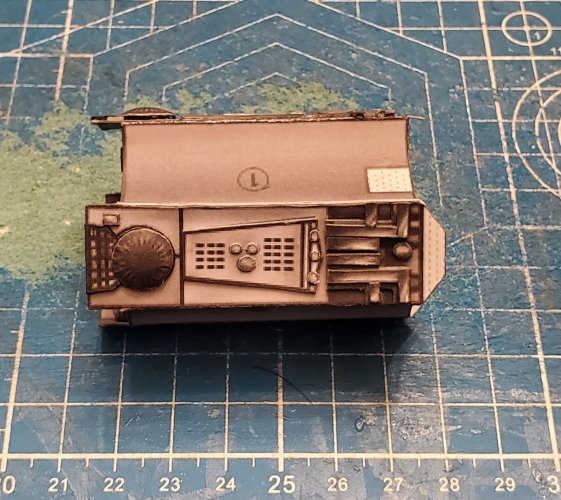
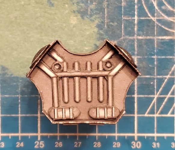
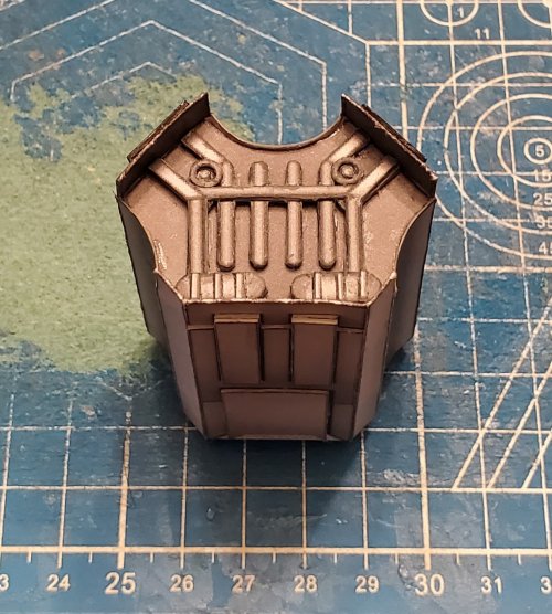
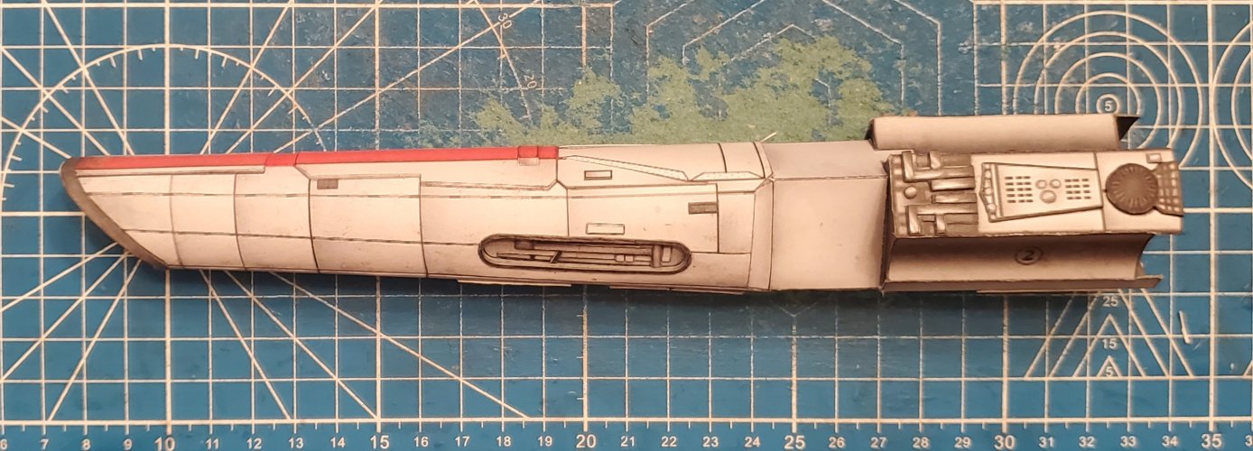
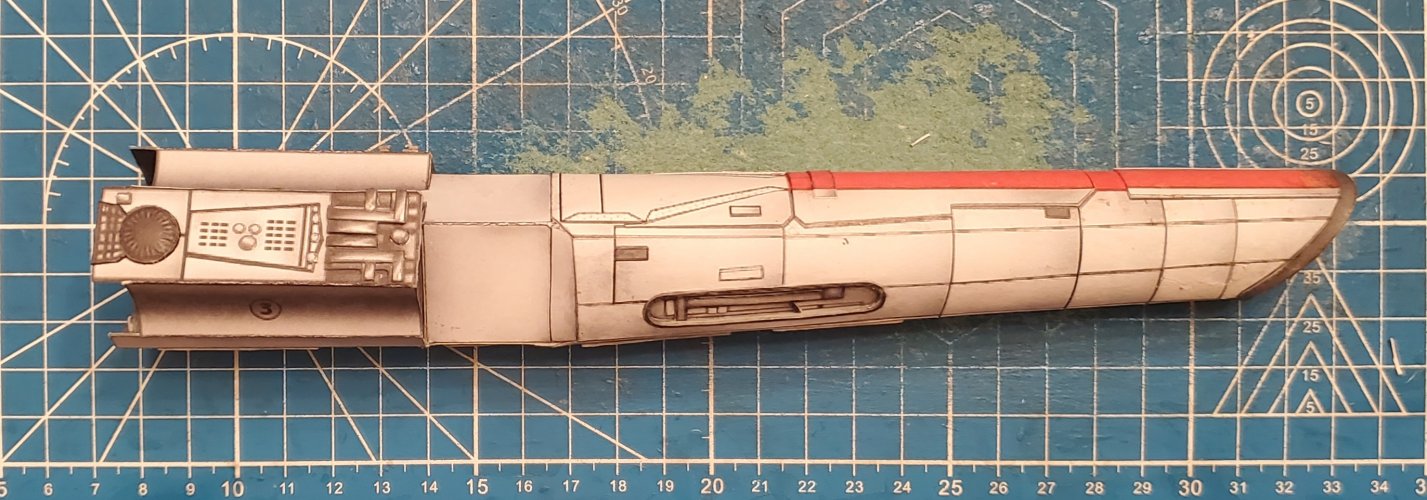
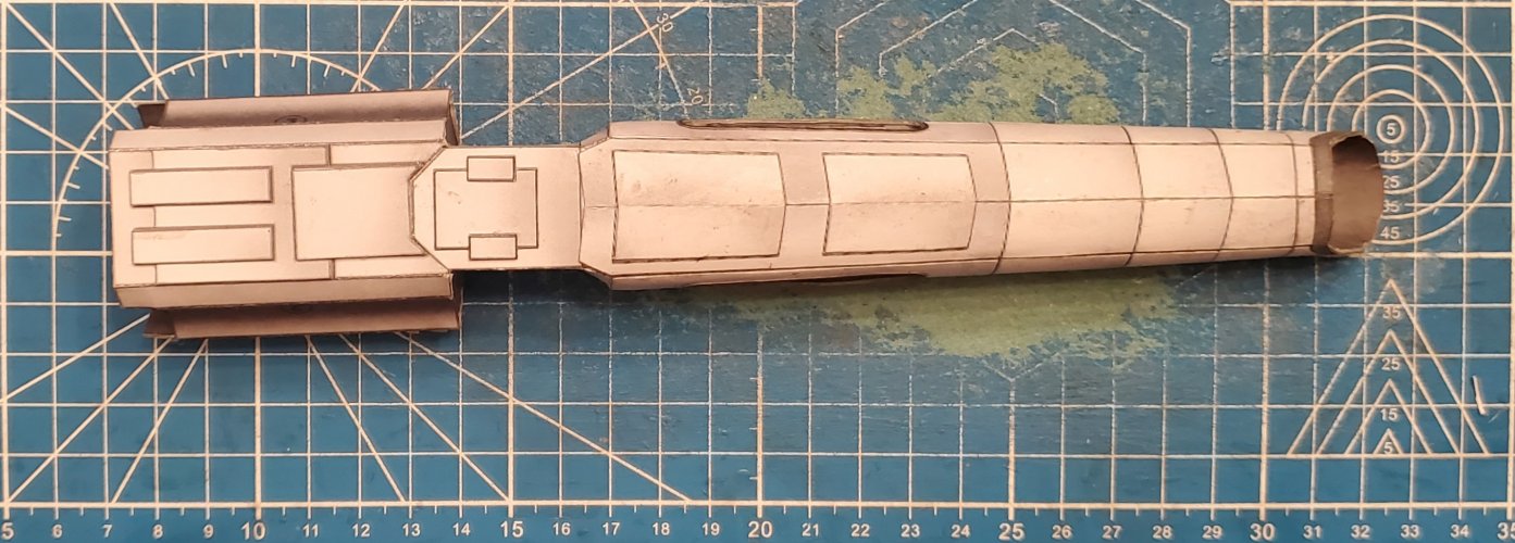
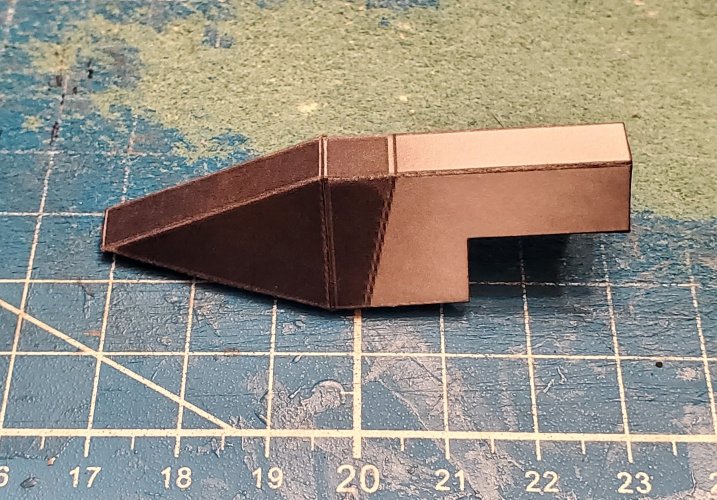
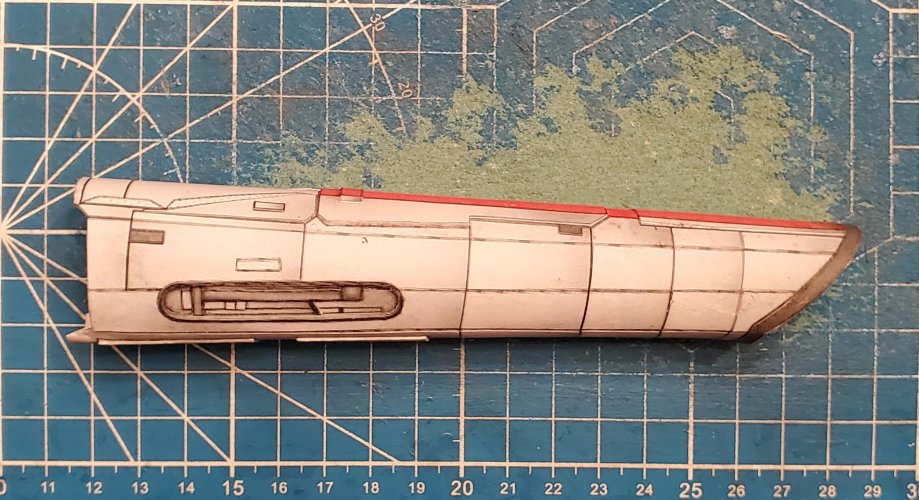
I have sealed the fuselage ad applied the raised panels and greebling.
20231229_182440.jpg

20231229_182500.jpg

20231229_182522.jpg

20231229_182535.jpg

Please stay tuned in to your local Colonial Broadcast Network for further updates and they happen.
 

zathros

*****SENIOR ADMINISTRATOR*****
Staff member
Administrator
Moderator
Apr 5, 2013
13,498
9,549
228
I've never seen panels welded on an aircraft, it's the overlap, and it starts from the back panel, working your way forwards, so that the air goes over the previous panel, allowing no moisture or air to get into any panel (they are usually recessed to the thickness of the panel), not on General aviation aircraft, as the aluminum is so thin. If you cut the Black panel lines out of the cover pieces to enhance the model, you would be surprised by how realistic the lines would look. I always cut on the line to try and remove any drawn panel line. The light shining, depending on the angle of the picture and ray tracing, would create the panel line. The dark line is not needed on the edge of the parts are not needed. However, you can't achieve that without the process that you are doing, (cutting panels to fit over the panel lines), it is well done though. IMHO.

Another way to enhance panel lines is to use a Pizza cutting wheel. This will recess the line, and give it a separate part texture, though technically it would be wrong. IMHO


1704056083233.jpeg
 

zathros

*****SENIOR ADMINISTRATOR*****
Staff member
Administrator
Moderator
Apr 5, 2013
13,498
9,549
228
When I worked on aircraft, a couple of times, due to aircraft hitting each other in the parking spaces, we would have to replace fuselage skin pieces. It wasn't difficult to do, but you did have to be careful. Most of these planes used conventional rivets, which mean someone had to be inside holding a square tool against the rivet while the Hammer gun on the other side pounded it into a flat head. Some newer aircraft now use pop rivets, which on some aircraft can take 9 G's of force.

When I started making paper aircraft, they were flying, gas engined R/C, so panel lines did not matter. When I moved back to display models, I was kind of appalled on how many panel lines were on some paper models. I understood the reason, and have seen outstanding models. I have yet to see a G.A. aircraft made with individual panels over a frame. It would be one heck of a model to build. Also, there's the question of would anyone actually build it?

I always wanted to build the plane I flew the most, the Piper PA180. It would take quite a bit of research and money to get actual blueprints to make a model to that level of authenticity. I think that's the general case for most models, so we use panel lines. You get a great model, for a lot less effort. ;)

Below is the model of the plane I had nearly 400 hrs. flight on. Lots of panels, but the panel lines are barely visible. It's a big pic, click on it and try and find the panel lines. :)

Piper_PA-28-180_Cherokee.jpg
 

micahrogers

Moderator "Where am I, and how did I get here?"
Staff member
Moderator
Jul 12, 2012
3,772
4,639
113
Shannon GA
Nice GA aircraft, only GA I've flown in was a Bell 212 for an aerial tour of New Orleans once. every thing else has ben military, or commercial aviation. As one who know what to look for, I can see most of the panels on that aircraft.
 

Rhaven Blaack

!!!THE MAN BEHIND THE CURTAIN!!!
Staff member
Administrator
Moderator
Jun 12, 2009
12,525
9,907
228
Oregon
www.deviantart.com
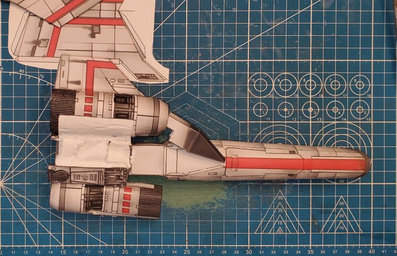
So, with my opening post for this thread, it illustrated the point of this thread and how to achieve the effect of "physical" panel lines in a model. I had initially thought about stopping there. However, since I had printed out the entire template of this model, I thought it best if I just continue the build. So, without further ado, here are the photos of my work thus far.

Here are the parts for the engine mounting block.
20240115_235946.jpg

Unfortunately, I (inadvertently) deleted the photos showing the construction of the Engine mounting block. So, here is the completed engine mounting block. However, as you can see in the previous photo, there are extra "Y" shaped pieces (the back face of the engine mounting block). I used those extra pieces as internal formers/supports for the engine mounting block.
(*NOTE* If you decide that you want to do this, make certain that you cut the tabs off that help support the front face piece.)

I raised the details and greebling.
20240117_113609.jpg

20240117_113642.jpg

20240117_113718.jpg

20240117_113743.jpg

20240117_114217.jpg

This is the connector between the fuselage and the engine mounting block.
20240117_121212.jpg

I attached the connector to the fuselage.
20240117_125212.jpg

I attached the engine mounting block to the connector.
20240117_141458.jpg

20240117_141523.jpg

20240117_141552.jpg

20240117_141608.jpg

Please stay tuned in to your local Colonial Broadcast Network for further updates and they happen.
 

Rhaven Blaack

!!!THE MAN BEHIND THE CURTAIN!!!
Staff member
Administrator
Moderator
Jun 12, 2009
12,525
9,907
228
Oregon
www.deviantart.com
Thank you both for the kind words!
Granted, the panel lines on this particular model are rather "over exaggerated". However, that is intentional for the illustration of the tutorial. If you were to build a model that had the proper panel line thickness, it would be rather difficult to see in a photo (but could still be felt by sensitive fingers).
 
  • Like
Reactions: Chuffy70

Rhaven Blaack

!!!THE MAN BEHIND THE CURTAIN!!!
Staff member
Administrator
Moderator
Jun 12, 2009
12,525
9,907
228
Oregon
www.deviantart.com
Continuing on with the engines.
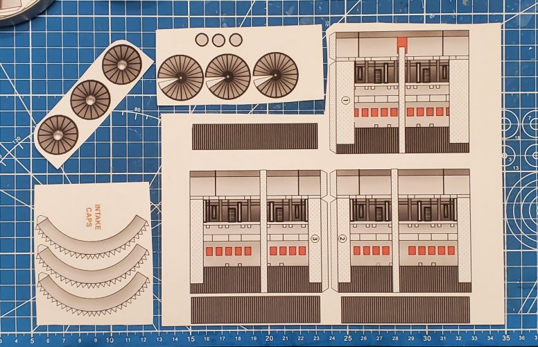
Here are the parts for the engine.
20240117_193321.jpg

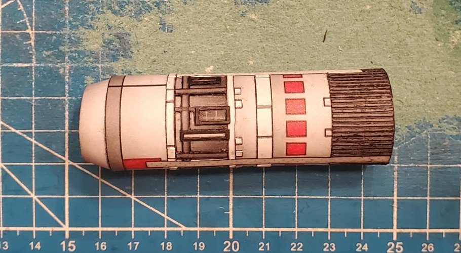
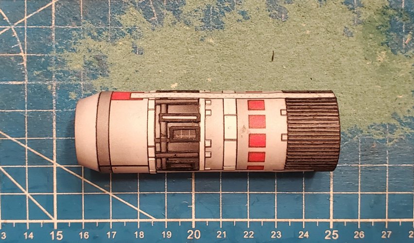
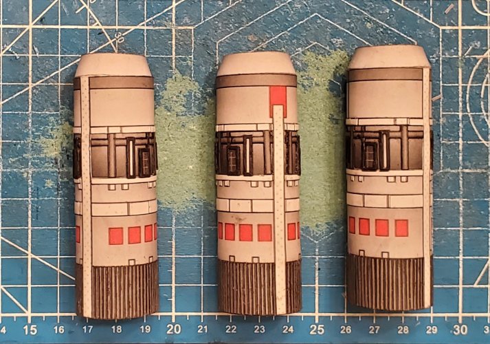
The engines are assembled. I have raised a few of the details and the strips on the exhaust.
20240118_183438.jpg

20240118_183446.jpg

20240118_225736.jpg

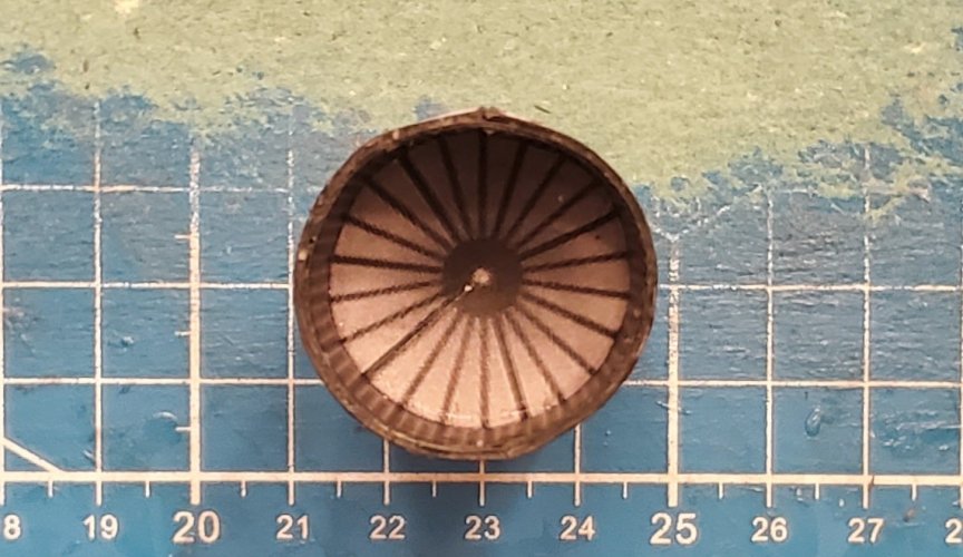
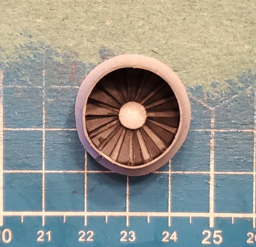
I louvered the fans.
20240118_225803.jpg

All three engines are complete.
20240202_062908.jpg

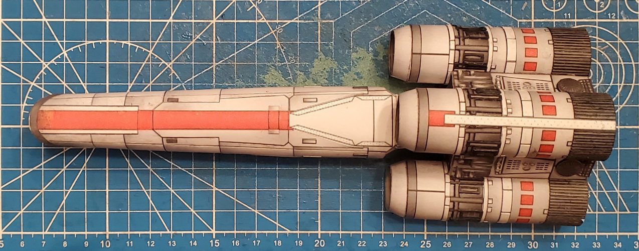
The engines are attached in place.
20240202_075027.jpg

Here is the canopy.
20240202_075159.jpg

The canopy is asembled.
20240202_083612.jpg

The canopy is attached.
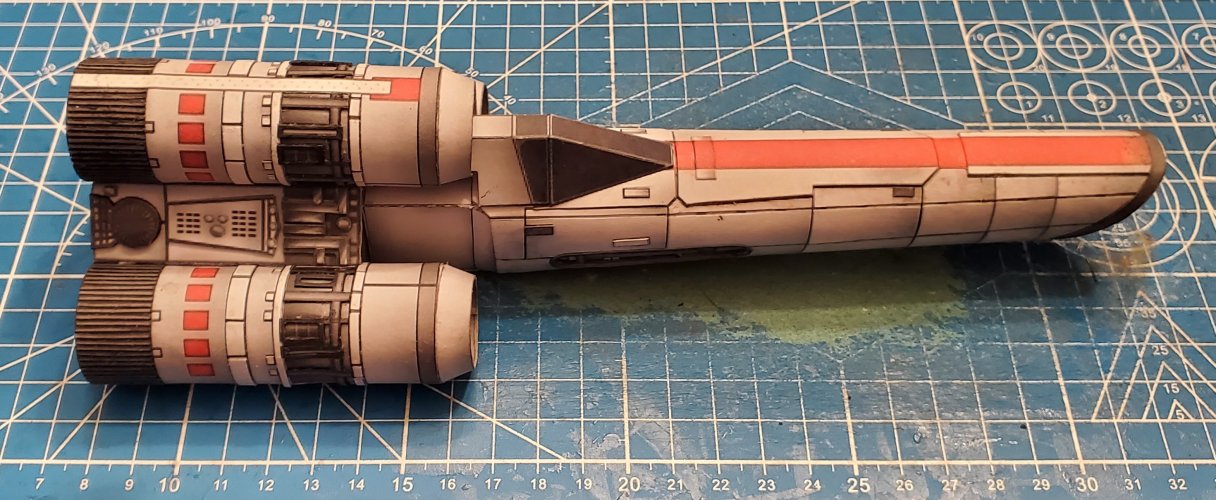
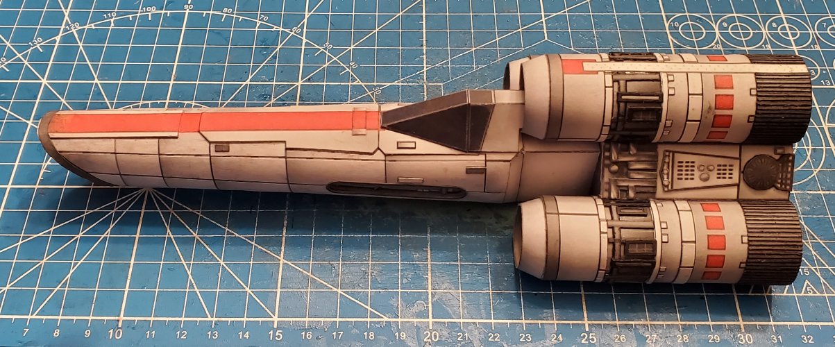
20240202_084304.jpg

20240202_084317.jpg

Please stay tuned in to your local Colonial Broadcast Network for further updates and they happen.
 

Revell-Fan

Co-Administrator
Staff member
Administrator
Moderator
Aug 1, 2009
11,612
12,353
228
Vreden
I see what you did with the thruster rings. I'm working on the template for the big one and am not sure how wide they are supposed to be. Thinking of laminating all these strips around the tube is giving me the chills..! :hammerhead:
 

Rhaven Blaack

!!!THE MAN BEHIND THE CURTAIN!!!
Staff member
Administrator
Moderator
Jun 12, 2009
12,525
9,907
228
Oregon
www.deviantart.com
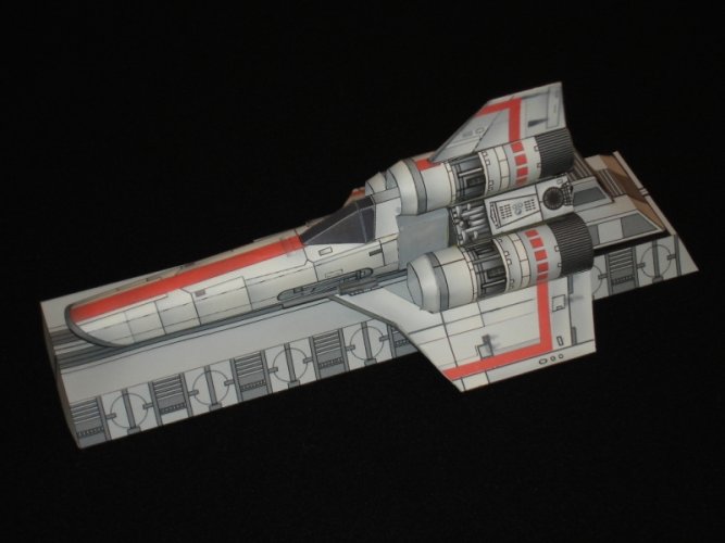
Since this project has fulfilled its purpose. I am not going to continue with it (by rebuilding it).
However, with that being said, I am working another project that entails repainting the Viper that this version was taken from:
Viper.jpg

Once I am finished with the repaint, I will upload the template.