So this is mainly a re-post of a thread I've had going for a bit over on WC News.com. I had gotten side tracked from working on it since... you know life and all that tends to come to a head. But working on the Marauder Bomber in a live stream has proven to be more motivational for me. So I'll be returning to this project in the not so distant future. So what project am I talking about? Well strap and get ready to launch!
Wing Commander 3: Heart of the Tiger is one of my favorite games of all times, and I absolutely loved piloting the Excalibur fighter in the game. So this is my effort to scratch-build a large scale (about 16" long) model of it. This is going to be a long term project. So this is going to be my project thread on here as I work through the project.
I did a paper-craft version of the F-109 Vampire recently, and that really rekindled an old interest I've had to have a model of the F-103 Excalibur.
Here is a gallery of images of the finished Paper-craft Vampire (will change link to forum hosted gallery once gallery is approved):
F-109 Vampire
I'll warn everyone now, this is going to take a while to complete. It will also be my first totally scratch built and self-designed model. The real challenge... I have no actual 3D design experience or systems. So I'm doing this all as I figure it out. Who wants to go on an adventure?
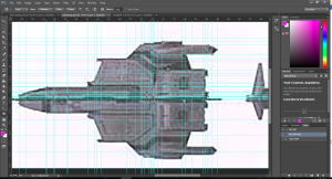
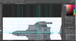
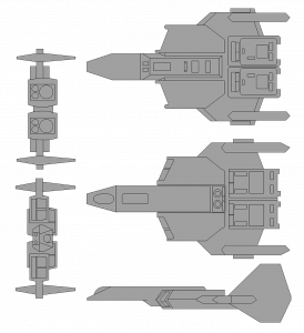
First thing I did was load up Wing Commander: Secret Opts and swap the in-game Excalibur with the Panther Fighter, that way I could control the fighter while I took screen caps of the fighter. So I took head-on shots of the craft from each of the axis angles. I then assembled those images into the collage you see here in Photoshop. I then used the full sized print out to gather measurements of the craft. here is the first batch of measurements.

This is the full size print out I assembled of the top-down shot of the Excalibur. Nothing particularly fancy here. Took the top down image, up-scaled it until it was the size I wanted (about 16" in length), and then printed it out. Cut the parts out and glued them together to get one sheet. From this I'm able to take measurements, which I record in the collage in photoshop.

I did use Pericles' paper-craft designs for the Vampire. The... I don't want to say the word but it's the only one I can think of, the 'problem' with Pericles' plans is they are quit literally the in-game model transferred to paper, which while it makes a game-accurate model, I'm shooting for something that is more universe accurate. The best example of what I mean on the Vampire can be seen in the nose:
If you look at the art work for the Vampire:

You can see it has a pair of twin-linked cannon barrel barrels (I want to say those would be the partial guns if memory serves based on placement).
But compare that to the nose of the in-game model:

You can see how the two barrels and assembly have been condensed down into what... well whatever that is. It's just something that didn't get translated from the artwork to the model or vice versa. Also the in-game vampire have a much leaner body thus appearing longer then in the art work.
For the Excalibur I want to go for display value. So I'll be interpreting and adding additional details, but I want to stay closer to the Wing Commander 3 version of the craft, but if I come to a point where I have a source of data from in-game compared to a source of data from say universe, unless I have an explicit reason to do other wise I'm going to take the source from in-universe as more accurate.
As I progress through the project I'm going to be posting a lot of information regarding how I go about things, how I got sizes, how I build parts, ect. I'm going to do this for a variety of reasons, and not all of them personal. As I said, I have no 3D design or architectural experience what so ever, I toyed with Miya for like 20 minutes once about 20 years ago, and have never had enough of an interest to go back into it. I've built.... the dark gods only know how many kit-models and I've converted hundreds more over the last 30 years, so I have a mind for "unfolding" things from their 3D construct to a 2d part. Still, there is a difference between knowing how to unfold an object and knowing how to build it.
So I will be posting pretty detailed progress updates on the project as I go both for a personal record so I can come back to it and see what I did, and to give people with more knowledge then I an opportunity to look at my process and provide feed back. And finally I'll post the detailed info as a basis for anyone else who wants to give it a go. I seek to inspire after all.
It was at about this point in my original thread on wcnews.com that a fellow Wing Commander fanatic chimed in. Whiplash has built several Balsa/Base wood models based on the Wing Commander series and had gone through a similar process designing the specs for his models as to what I was attempting to do. The big thing he pointed out was due to the limitations of the technology at the time the in-game models are very poor sources of accurate measurement information and he urged me to other assets to get my measurement information.
so I took Whiplashs suggestion, well the first part of it anyway since this is most certainly not going to be a quick process, and shifted gears from using the in-game models for size and measurements, and instead using alternate imagery, such as the Warbirds file info on the Excalibur. I also grabbed a metric crap ton of frames from the Kilrathi Saga intro and several in game videos from Wing Commander 3 showing the Excalibur. For the moment they are just sitting my library and due to the video shots they will be of little use for getting measurements. But as Whiplash suggested, they should be a good option for detail checks and the like. I've loaded the assorted collection of frames to my photobucket account, which you can view here. I've also gone back through my library of pictures (I've been collecting images from the internet ever since I discovered the "Save image as" command when I was about 12 years old) and collected several images I have of various artistic renderings of the Excalibur. Like the Screen Stills, I'm not sure how much measurement value these will have, but again they provide details that aren't as visible in the smaller images or the in-game shots. These images can be viewed here. if anyone identifies where the respective image is from, please drop me a line so I can add the info to the images in my photobucket. I do want to give credit to the artists who made the images.http://s14.photobucket.com/user/mav...03 Excalibur/Artistic Reference?sort=3&page=1
Beyond all of that I did start crunching some numbers for the model again based on the Warbird images. I've decided I'm going to scale back a bit for the project and rather then do a 16" long model, I'm going to do a 12" long model instead. I've done lots of small scratch build jobs before, but never a full blow from the ground up total scratch built model before. And I'm thinking about doing some lighting effects in the model as well. So the 12" version will be easier to manager and I think closer to my skill set at present. I want to challenge myself, not waste my energy and materials.
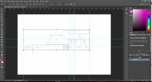
So, I took the warbirds image and pulled it into Photoshop where I upped the size by a factor of 6 so I have some room to work and make notes. The image is small enough that I will be forced to 'interpret' a lot of details, but that's what the reference library is for. With the image in Photoshop I started working out some numbers. I had to go way back to Algebra and Geometry to remember how to work with scales and conversions for this and I'm not totally sure my math is accurate. So if anyone who actually knows what they are feel see a mistake, please point it out.
Here is what I have:

Whiplash then provided some more information about scale calculations and such. A lot of it went over my head as to the practical use of it due to the size of the image itself. The printed image is 3/4" wide after all. But it did spark a thought in my mind.
I'll explain:
Wing Commander 3: Heart of the Tiger is one of my favorite games of all times, and I absolutely loved piloting the Excalibur fighter in the game. So this is my effort to scratch-build a large scale (about 16" long) model of it. This is going to be a long term project. So this is going to be my project thread on here as I work through the project.
I did a paper-craft version of the F-109 Vampire recently, and that really rekindled an old interest I've had to have a model of the F-103 Excalibur.
Here is a gallery of images of the finished Paper-craft Vampire (will change link to forum hosted gallery once gallery is approved):
F-109 Vampire
I'll warn everyone now, this is going to take a while to complete. It will also be my first totally scratch built and self-designed model. The real challenge... I have no actual 3D design experience or systems. So I'm doing this all as I figure it out. Who wants to go on an adventure?
First thing I did was load up Wing Commander: Secret Opts and swap the in-game Excalibur with the Panther Fighter, that way I could control the fighter while I took screen caps of the fighter. So I took head-on shots of the craft from each of the axis angles. I then assembled those images into the collage you see here in Photoshop. I then used the full sized print out to gather measurements of the craft. here is the first batch of measurements.
This is the full size print out I assembled of the top-down shot of the Excalibur. Nothing particularly fancy here. Took the top down image, up-scaled it until it was the size I wanted (about 16" in length), and then printed it out. Cut the parts out and glued them together to get one sheet. From this I'm able to take measurements, which I record in the collage in photoshop.
I did use Pericles' paper-craft designs for the Vampire. The... I don't want to say the word but it's the only one I can think of, the 'problem' with Pericles' plans is they are quit literally the in-game model transferred to paper, which while it makes a game-accurate model, I'm shooting for something that is more universe accurate. The best example of what I mean on the Vampire can be seen in the nose:
If you look at the art work for the Vampire:
You can see it has a pair of twin-linked cannon barrel barrels (I want to say those would be the partial guns if memory serves based on placement).
But compare that to the nose of the in-game model:
You can see how the two barrels and assembly have been condensed down into what... well whatever that is. It's just something that didn't get translated from the artwork to the model or vice versa. Also the in-game vampire have a much leaner body thus appearing longer then in the art work.
For the Excalibur I want to go for display value. So I'll be interpreting and adding additional details, but I want to stay closer to the Wing Commander 3 version of the craft, but if I come to a point where I have a source of data from in-game compared to a source of data from say universe, unless I have an explicit reason to do other wise I'm going to take the source from in-universe as more accurate.
As I progress through the project I'm going to be posting a lot of information regarding how I go about things, how I got sizes, how I build parts, ect. I'm going to do this for a variety of reasons, and not all of them personal. As I said, I have no 3D design or architectural experience what so ever, I toyed with Miya for like 20 minutes once about 20 years ago, and have never had enough of an interest to go back into it. I've built.... the dark gods only know how many kit-models and I've converted hundreds more over the last 30 years, so I have a mind for "unfolding" things from their 3D construct to a 2d part. Still, there is a difference between knowing how to unfold an object and knowing how to build it.
So I will be posting pretty detailed progress updates on the project as I go both for a personal record so I can come back to it and see what I did, and to give people with more knowledge then I an opportunity to look at my process and provide feed back. And finally I'll post the detailed info as a basis for anyone else who wants to give it a go. I seek to inspire after all.
It was at about this point in my original thread on wcnews.com that a fellow Wing Commander fanatic chimed in. Whiplash has built several Balsa/Base wood models based on the Wing Commander series and had gone through a similar process designing the specs for his models as to what I was attempting to do. The big thing he pointed out was due to the limitations of the technology at the time the in-game models are very poor sources of accurate measurement information and he urged me to other assets to get my measurement information.
so I took Whiplashs suggestion, well the first part of it anyway since this is most certainly not going to be a quick process, and shifted gears from using the in-game models for size and measurements, and instead using alternate imagery, such as the Warbirds file info on the Excalibur. I also grabbed a metric crap ton of frames from the Kilrathi Saga intro and several in game videos from Wing Commander 3 showing the Excalibur. For the moment they are just sitting my library and due to the video shots they will be of little use for getting measurements. But as Whiplash suggested, they should be a good option for detail checks and the like. I've loaded the assorted collection of frames to my photobucket account, which you can view here. I've also gone back through my library of pictures (I've been collecting images from the internet ever since I discovered the "Save image as" command when I was about 12 years old) and collected several images I have of various artistic renderings of the Excalibur. Like the Screen Stills, I'm not sure how much measurement value these will have, but again they provide details that aren't as visible in the smaller images or the in-game shots. These images can be viewed here. if anyone identifies where the respective image is from, please drop me a line so I can add the info to the images in my photobucket. I do want to give credit to the artists who made the images.http://s14.photobucket.com/user/mav...03 Excalibur/Artistic Reference?sort=3&page=1
Beyond all of that I did start crunching some numbers for the model again based on the Warbird images. I've decided I'm going to scale back a bit for the project and rather then do a 16" long model, I'm going to do a 12" long model instead. I've done lots of small scratch build jobs before, but never a full blow from the ground up total scratch built model before. And I'm thinking about doing some lighting effects in the model as well. So the 12" version will be easier to manager and I think closer to my skill set at present. I want to challenge myself, not waste my energy and materials.
So, I took the warbirds image and pulled it into Photoshop where I upped the size by a factor of 6 so I have some room to work and make notes. The image is small enough that I will be forced to 'interpret' a lot of details, but that's what the reference library is for. With the image in Photoshop I started working out some numbers. I had to go way back to Algebra and Geometry to remember how to work with scales and conversions for this and I'm not totally sure my math is accurate. So if anyone who actually knows what they are feel see a mistake, please point it out.
Here is what I have:
Whiplash then provided some more information about scale calculations and such. A lot of it went over my head as to the practical use of it due to the size of the image itself. The printed image is 3/4" wide after all. But it did spark a thought in my mind.
I'll explain: