

There seems to be a lot of modelers that haven’t gone over to DCC. We took a poll a while back and the split was about 50/50. I can see the advantages and the features of using DCC since I spent a good 40 years building digital control systems. I’ve chosen to stay with DC since my N scale layout is relatively small (about 32 sq. ft.) and there’s not going to be more than one or two consists operating at any one time. It’s economics as well, and I know I’m not alone in that regard.
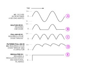
Anyway, I’ve seen many questions here regarding DC power packs, so I’ve put together a few diagrams that might be helpful in explaining some basic concepts of DC. Someone recently posted a primer on basic electricity, voltage, current and resistance so it might be helpful in reading that as well. The diagram below shows what different voltage sources do over time. If you had an oscilloscope connected to these power sources, this is what you would see; the technical term for that is called a “waveshape”. It represents what the voltage measurement is at any point in time. For example, waveshape “A” is pure AC, just like what comes out of a wall outlet. The voltage starts at 0 and slowly increases to some value before it goes back to zero and reverses itself and goes negative and equal amount. The frequency it does this at is called Hertz. The basic frequency in North America is 60 Hz, while across the pond and in OZ it becomes 50 Hz. We can thank George Westinghouse for coming up with this concept; Edison would have had us all running on DC if he got his way. Now, in order to get this voltage to be reduced, one must use a transformer. This will reduce the wall outlet voltage from say, 120 volts, to something more usable, like 12 or 18 volts. There are times when this is enough, like running some Lionel O gauge, or operating lamps or other accessories and for switching turnouts. There are times when AC won’t work and DC is required, like running most other scale engines and all electronics. Waveshape “B” shows what happens when you add a diode to the circuit. A diode, or rectifier, will only allow current to flow in one direction. By placing this in series with the load, the result is that the negative half of the cycle is blocked. You will find this on most cheap power packs that come with your basic train set.
An improvement on that is shown in waveshape “C”, where by using four diodes, it is possible to flip the negative half-cycle and not have the blank space, or 0 volts for that portion of the cycle. I’ve got an early model MRC that uses this. Both these methods are OK for running trains, but are unreliable since the voltage will vary with the load. If you add a capacitor to “C”, then you get what you see in “D”, filtering and a little more stability. The little squiggles are called ripple. What is happening is that the capacitor charges up like a small battery and slowly discharges. The next part of the cycle causes it to charge up again. The amount of ripple is dependent on the size of the capacitor and the amount of the load. The load still has some affect on the voltage output here as well.
Waveshape “E” shows what pure regulated DC looks like. It’s accomplished by adding some electronics and some more filtering to “D” so that the voltage remains constant regardless of the load, the same as you get from a battery. Most engines don’t need that kind of regulation, but most electronics do.
 although I think it's unlikely since someone else would eventually had to take us in that direction.