Zedob's Layout Party

zedob

Member
Dec 26, 2004
757
0
16
62
Chicopee, MA
Next installment.

Ok, I didn't do a whole heck of alot. Just adding more staining and weathering to the stone work.

Like I had mentioned earlier, I wanted to paint the mill foundation to simulate the coloring on the prototype mill, so here it is. I haven't added the green fungus yet, but it's coming.:rolleyes:

Pic #1, prototype
Pic #2, model mill before staining
Pic #3 & 4, what it looks like now
 

Attachments

  • Copy of mill 001.jpg
    Copy of mill 001.jpg
    11.5 KB · Views: 104
  • Copy of overall.jpg
    Copy of overall.jpg
    14.5 KB · Views: 98
  • stained.jpg
    stained.jpg
    16.2 KB · Views: 100
  • Copy of mill 015.jpg
    Copy of mill 015.jpg
    19.7 KB · Views: 107

Art67

Member
Apr 18, 2005
192
0
16
57
Baltimore
Looks like you are making excellant progress, Zedob. I am impressed with how you have managed to to create multiple tiers of scenery layers. I think that that is why New England, with all its streams, bridges, trees and factories all densely packed along one another, is such a modeling inspiration, and I think you are capturing it quite nicely. I have always wanted to try out tube watercolors for buildings, and after seeing how yours came out, I will do so on my next project. Great Job, Stuart.
 

zedob

Member
Dec 26, 2004
757
0
16
62
Chicopee, MA
Thanks,

I actually used a mix of stains and paints. I used the tube watercolor paint to make the WS stain redder, but it was a tad bit too red. I had a mix of Floquil boxcar red with some other colors that I had from a previous project that ended up being perfect for the red/ brown base shade I was trying to duplicate from the proto. It also had covering power because I didn't want any plaster highlights showing through. I brushed it on, hopping around randomly until it was sufficiently covered. I then came back with a wash of Guilford grey and went over the whole thing, giving heavier treatment here and there.

The next step is to put some mortar on the bricks and dry it up a little with some chalks.
 

Jac's Lines

Member
Jan 28, 2005
152
0
16
52
Rochester, NY
Some excellent and inspiring modelling going on here. We've got a number of similar water-based industrial sites in my neck of the woods, and you've got the look down. I can't wait to see that mill run with some whitewater coursing through it. Cool stuff.
 

Petervan

New Member
Nov 7, 2005
41
0
6
67
Lakehurst NJ
The detail looks great. How did make the stone work? is a model kit?
thumbsup.gif
 

zedob

Member
Dec 26, 2004
757
0
16
62
Chicopee, MA
Jac's Lines, I'm happy to see that I'm on the right track. It's not a model of any particular mill, but a conglomeration of different ones i have seen around here.


Petervan, Thanks. The stonework is from my product line, which you can check out through the link below (if you haven't already). Basically, alot of hours staring at pictures of prototype stones and through a microscope while picking away at blank stone strips.

As for the next installment, well, not much right now. Not that I haven't been working on anything, I've been testing some water materials and painting rocks. The best I can do at this time is this one pic of how the stonework looks after I dusted it/them down with pastel chalks to kill the shinyness(sp) left behind by WS's "flat drying" scenic cement:rolleyes: . The results ended up rather nicely. I used white, which helped give it that effervescence (sp) look.

I probably won't get to pour water for a couple of days. Even if I do, I don't plan on doing it in one night. The water is one project I'm going to take slow.:thumb:
 

Attachments

  • pre-water.jpg
    pre-water.jpg
    22.3 KB · Views: 119

zedob

Member
Dec 26, 2004
757
0
16
62
Chicopee, MA
Zedob’s Layout Party

Installment IV

I’m finally starting to see the light at the end of the tunnel in respect to adding water to the scene, but I keep finding things I need to do before I actually add the water. I wasn’t quite sure what water modeling technique to use, so I did a bit of final searching through some past threads and determined that I wasn’t going to use one exclusively because I think each system has it’s merits and should be used accordingly to give the desired effects.

This particular scene is rather flat due the fact that the hidden track that I’m trying to hide is set at a certain height, so a super cascading waterfall it is not going to be. With this in mind, the highest point of the modeled water will be no more than 1” (25mm). I wanted the water to be interesting, but more importantly, realistic. So, back to the resource files.

Most rivers (around here) are a mix of white and dark deep-pooled water. The white is just turbulent aerated/bubbled water and can be generated by a stick if the velocity of the water is high enough. The bubbles dissipate rather quickly and there is usually darker pooled, or low velocity, water right next to it. Of course, this is all dependent on the amount of water flow, too. During the spring melt there is so much volume of water flowing that everything is whitewater. Where as during low water or dry conditions there may be stagnant pools in natural potholes that may be disassociated with the original river, which may be just a trickle of water barely creating any white water.


Attachments

  • Copy of collins_co_east_upclose.jpg
    Copy of collins_co_east_upclose.jpg
    10.6 KB · Views: 123

zedob

Member
Dec 26, 2004
757
0
16
62
Chicopee, MA
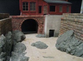
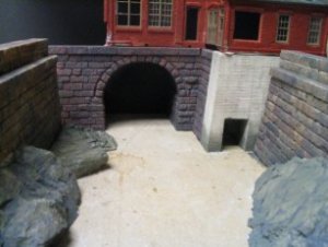
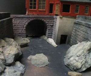
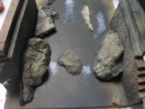
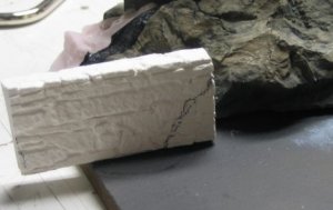
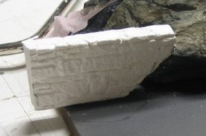
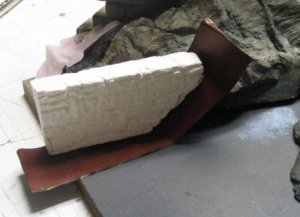
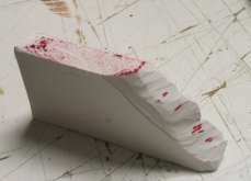
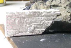
What I had in mind was to come out of the tunnel with a turbulent, but relaxed, water flow. From there it would dump into a larger area, or deep pool thus reducing its velocity. The tail water from the turbine house will dump into this pool, also. To give credence to the pool I placed a plaster stone that had it’s back flattened by rubbing it on a piece of sandpaper laid out on the table, between the two major rock outcroppings that opposed each other from each bank.

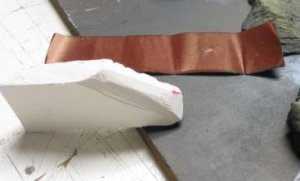
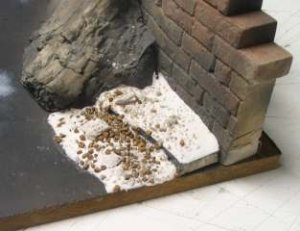
This creates a weir effect. Instead of one big flow I divided it into two smaller flows, which will deliver their contents into the area at the front of the layout. Since I have to follow some basic physical properties like “water flows downhill”, I decide to do the two sections in front of the tunnel in two pours. The first pour would cover both areas. The second pour would be from the tunnel to the double spit.

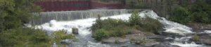
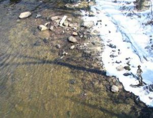
I had noticed that in cases like the split, water rolls over the obstruction, and then makes white water. In other words, I wanted the “fake” water to maintain a meniscus or surface tension. I was able to do this with as thick pour of gloss medium, but GM doesn’t like large thick areas and will split and crack, which may be useful in the future on another project, but it wasn’t going to hack it here.

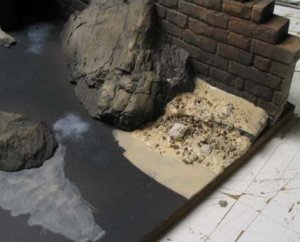
I have a bottle of WS water, which I am going to test before messing up my diorama, but from what I’ve read from other modeler’s experience, it might be the ticket. 1/8” pours are exactly what I’m looking for, as long as I can get the material to stop at the two tight spots in the split.
 

Attachments

  • pre-water-11.jpg
    pre-water-11.jpg
    8.4 KB · Views: 118

zedob

Member
Dec 26, 2004
757
0
16
62
Chicopee, MA
Now that I have the water plan under control…

I had to finish up on the transition from the fill, the abutment and the natural features of the river. I really don’t care for the stone abutment sitting right on the bedrock look, even though that is exactly what would have been done, but rather the look of years of dirt, crud and vegetation creating the transition.

On the lower left of the scene I had a 45 degree slope of dirt from the fill that would have ended up farther into the river than I intended it to go, so I cut out a small piece from a random stone retaining wall casting I had laying around :rolleyes: and placed it to help keep the fill from falling into the river.
 

Attachments

  • randomstonewall.jpg
    randomstonewall.jpg
    21.1 KB · Views: 120
  • randomstonewall-2.jpg
    randomstonewall-2.jpg
    15.4 KB · Views: 121

zedob

Member
Dec 26, 2004
757
0
16
62
Chicopee, MA
However, not being one to let it go right there, I decided to “fit” the wall to the rock outcropping. With the help of some “articulation paper” I was able to get a good tight fit. Articulation paper (AP) is a common item in a dental office. The doctor uses it to check contact when inserting crowns, bridges and such, between adjacent and opposing teeth. Ask your dentist if you can bum a few pieces from him/her.

It is nothing more than double sided carbon paper. The kind I use is black on one side and red on the other, but you can get them in all kinds of colors. It doesn’t really matter, as long as you use it correctly, which means rubbing it in (see pic) then cutting or grinding away the high spot indicated by the colored mark (see following pic). Nothing special, it's the same way the Egyptians made razor tight joints between the stones in the Pyramids, except I don’t think they had rolls of (AP) to help them.:D
 

Attachments

  • stoneretainingwall-5.jpg
    stoneretainingwall-5.jpg
    13.3 KB · Views: 117
  • stoneretainingwall-6.jpg
    stoneretainingwall-6.jpg
    7.9 KB · Views: 118

zedob

Member
Dec 26, 2004
757
0
16
62
Chicopee, MA
As you can see from the following pics, the more I marked and trimmed, the more marks appeared. Note: I didn’t mess with the marks on the bottom, which are shown on top in this pic.
 

Attachments

  • stoneretainingwall-7.jpg
    stoneretainingwall-7.jpg
    3.9 KB · Views: 117

zedob

Member
Dec 26, 2004
757
0
16
62
Chicopee, MA
It takes longer than cutting and slapping it up in place, but it’s worth the effort.
 

Attachments

  • stoneretainingwall-8.jpg
    stoneretainingwall-8.jpg
    10.6 KB · Views: 117

zedob

Member
Dec 26, 2004
757
0
16
62
Chicopee, MA
I wanted the riverbank area directly in front of the viewer to look something like this. I knew I could get it to look fairly close to this using gloss medium, but I felt it would look better if I used the WS water instead. I needed to work on the transition between the abutment and river and figured that sand would have eventually been thrown into this area by the eddy action of the water over time.
 

Attachments

  • river_water.jpg
    river_water.jpg
    23.2 KB · Views: 114

zedob

Member
Dec 26, 2004
757
0
16
62
Chicopee, MA
I mixed a thin mix of Hydrocal and poured a small amount in that area and then with a pencil I pushed it around into the corners. After I was happy with the arraignment I rapped the worktable with a hammer to settle the plaster down into a more natural shape. I added some WS medium size brown ballast to the plaster bank while it was still wet and then after a few minutes I pushed the ballast down into the plaster, so it looked as though the rocks were filled in with accumulated sand.
 

Attachments

  • rhbank-2.jpg
    rhbank-2.jpg
    10.7 KB · Views: 113

zedob

Member
Dec 26, 2004
757
0
16
62
Chicopee, MA
I gave everything some time to dry then applied a diluted coat of aged concrete with a dab of dirt colored paint. It actually looks better in real life and should look much better once I set up for a “real” pic. The other pics show the other areas where I repeated the process.

The lousy transition from the sand to the deep dark water will be remedied with the airbrush before any water is added.
 

Attachments

  • rhbank-3.jpg
    rhbank-3.jpg
    16.8 KB · Views: 112
  • sandbar-2.jpg
    sandbar-2.jpg
    13.7 KB · Views: 113

zedob

Member
Dec 26, 2004
757
0
16
62
Chicopee, MA
Thanks guys, I wanted to work on it today, but the gods had different plans. I've been chomping at the bit all day long. I was hoping to get something done, but it didn't happen.:rolleyes:

I like to hyper focus when working on projects like this otherwise there's a chance for something else coming up and distracting me. Having a deadline has been a real help. :thumb: Of course there are drawbacks like, being totally engrossed in this project and not taking care of other's.:rolleyes:

If we do this more often, I may be able to finish my layout in less than a year.:D