Willys Jeep from Modelik

Status
Not open for further replies.

lriera

Member
Aug 28, 2007
183
0
16
70
Barcelona - Spain
Hi all,

This time it is called to pass through my workshop the Willys Jeep from Modelik.

Historical frame
The history of the Jeep begins the 11 of 1940 July when the Army of the EE.UU summoned 135 car manufacturers to participate in the contest to design a hybrid vehicle of adaptable general intention to recognition missions and control. 49 days were granted to them to present/display the proposals of design and 75 to make the first 70 prototypes.

Only three companies accepted American Bantam Car Company, Ford Motor Company and Willys-Overland Motors and of them, Bantam was the unique one that was able to display a vehicle of test in 49 days and models of production in 75.

Nevertheless due to the precarious economic situation of Bantam, the Government of the EE.UU decided that this one yielded the planes to the other two companies and in November of 1940 these displayed their own prototypes, which turned out to be very similar, reason why 1,500 units were in charge of test to each one.

In July of 1941 it adjudged to Willys the order of 16,000 units of his design, mainly, to the greater power of his motor. Nevertheless in October of 1941 it was evident that single Willys could not satisfy the demand of units of the vehicle, reason why also the production of the model was in charge to Ford.

During the World War II, Willys produced 363,000 units and Ford 280.000. Approximately 51,000 of these vehicles were exported to Russia based on the Lend-Lease program, which was the denomination under which enormous amounts of military equipment were provided to the allies of EE.UU.

Where comes from the Jeep word?
There are different histories about the origin from the Jeep term. One talks about to that Ford used denomination GP for his first models of this vehicle. And in English initials GP they are possible to be read like Jeep. Another history talks about to that the soldiers during the World War I denominated “jeep” to the inexperienced recruits who had still not received formation or to any piece of equipment that had still not passed the burn in. Still another history talks about to its origin in “Eugene the Jeep” a personage who accompanied Popeye and that was able to cross rivers, to raise mountains, etc. The soldiers gave this denomination to the new vehicle by their impressive similar capacities.

References:
Willys MB - Wikipedia, the free encyclopedia
Jeep - Wikipedia, the free encyclopedia
Official Jeep Site - 4x4 SUV, Sport Utility Vehicle

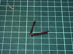
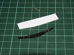
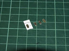
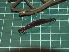
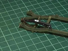
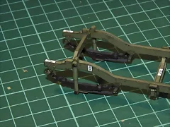
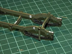
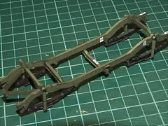
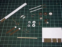
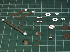
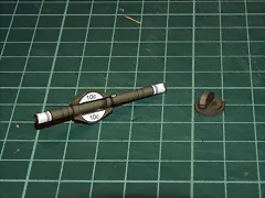
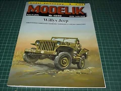
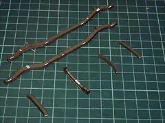
and after this historical review, in Picture 1 I show the model to you. It is notebook 2002 10 from Modelik.

1.

This is all at this moment, more to come soon.

Bye.
 

lriera

Member
Aug 28, 2007
183
0
16
70
Barcelona - Spain
Hello to all,

I am very happy to participate at the Forum with this build. Now I am beginning with the assembly of the model.

In Picture 2 you can see already cut all the pieces that will compose the vehicle’s frame. In Picture 3 the four pieces which the longitudinal stringers of vehicle frame consist are sticking (front and back).

2. 3.

In Pictures 4, 5 and 6, once droughts the stringers, I come to stick the two longitudinal strips that cover them. You can see that I have painted green all the edges of the paper, the surface of the stringers and the edge of the strips. In this occasion, and unlike with the Kettenkrad, I have found a marker that looks like the green printed original color.

4. 5. 6.

In Picture 7 you can see the stringers with the strips both front and back. In Pictures 8 and 9 also mounted the crosspieces that will compose the vehicle’s frame.
7. 8. 9.

Next the frame is due to mount; it is necessary to join the stringers with the crosspieces. This is a very difficult job and I think that I have found a very easy method to fix all the pieces.

Tell me what it seems to you, please. More to follow soon.

Greetings.
 

lriera

Member
Aug 28, 2007
183
0
16
70
Barcelona - Spain
Hello to all,

Next you can see how it is the device that I have improvised, more cheap impossible. A synthetic cork base of which is protected any electronic device and a few needles. I have used needles of modelism, but any others can do. The synthetic cork comes always perfectly smooth and flat. In Pictures 10 and 11 different views of the initial disposition. Both lateral of the frame already “nailed” with the needles to the synthetic cork. I have taken the separation measures with the crosspieces and I have aligned them with a small metallic rule.

10. 11.

In Picture 12 the crosspieces of the ends are sticking. And in Picture 13 also the third crosspiece is sticking. Finally in Picture 14 you can see the frame with the glue dry, on the work table. Incredible! Easier impossible, it has been perfectly aligned and without torsion, the four ends touch all flat on the table.

12. 13. 14.

The emotion that I have felt when I have been unnailing the needles, I have removed the frame from the “shipyard” and have seen that it was perfectly aligned, has been one I never will forget.

Please tell me what it seems to you.

Greetings.
 

KCStephens

Member
Sep 18, 2007
83
0
16
57
York, PA
It looks like your off to a good start with the jeep. I like the way you glued up the frame using pins and a piece of foam. Very similar to the way you build stick and tissue airplanes. Keep up the good work:thumb:
 

lriera

Member
Aug 28, 2007
183
0
16
70
Barcelona - Spain
Hello companions,

Dansls1, Kenlwest, HeavyKevie, Nemesis7485, Rlwhitt, thank you for your kind words.

Here I am again with another progress on the Willys Jeep. This time is the piece that holds the hook of tow to the frame of the vehicle and the two back crossbows; I leave the front crossbows for the coming day. On Picture 15 you can see the parts that compose the subjection piece of the hook. And on Picture 16 the piece already mounted, ready to be beaten to the frame. On Pictures 17, 18 and 19 different views from the frame with the piece glued.

15. 16.

17. 18. 19.

On Picture 20 the different pieces that compose a crossbow already cut. These are of one of the back crossbow; the front ones have some pieces more. On Picture 21 already I have stuck the strips that form the pyramid, on them the two final pieces that lack one with the coiled ends that are the subjections of the crossbow and the other that is the top cover. The 1 mm cardboard piece is the “mold” on which they are formed the pieces that compose each crossbow, to obtain that typical “doubled” form of the automobile crossbows. On Picture 22 the crossbow already has all the stuck pieces and I have also painted them. In this case I have used a black marker. The four pieces of each side are the ring of subjection of the pieces of the crossbow. On Picture 23 I have already stuck those rings to the crossbow and on Picture 24 I have painted everything with the black marker.

20. 21.

22. 23. 24.

On Pictures 25 and 26 I show to you the assembly of the second crossbow with other steps different from first, so that its building process will be better understood.

25. 26.

And on Pictures 27 and 28 you can see the second crossbow held with the needles, so that the openings of the ends are to the same distance and are of the same diameter.

27. 28.

I hope that the explanations are interesting to you and that you will say what it seems to you.

Greetings, bye.
 

lriera

Member
Aug 28, 2007
183
0
16
70
Barcelona - Spain
Hello to all:

Here I am with more of the same. More crossbows. This time is the front crossbows. These have four pieces plus each one and somewhat greater difficulty at the time of sticking them to the frame.

On Picture 29, you can see all the pieces that compose the two front crossbows. To the left of the Photography also are those that conform the shock absorbers, those are the pieces of green color. In Pictures 30 and 31 a crossbow already mounted with two different views so that you prune to appreciate well the form in which I have stuck with them.

29. 30. 31.

On Picture 32 two crossbows already mounted and placed in the pins so that the distances and diameters of the holes of their ends are equal. And On Picture 33 two finished crossbows with the edges partially painted.

32. 33.

On Picture 34 you can see how I stick the strips that are going to become retaining rings of each crossbow. Soon I am coiling each strip on itself. On Picture 35 I already have finished with the rings of one crossbow. On Picture 36 and 37 both crossbows almost finished and painted.

34. 35. 36. 37.

On Picture 38 you can see the small pieces that constitute the subjection of the crossbows to the frame. On Picture 39 I have painted with the green marker the edges of all those pieces and On Picture 40 the finished assembly of crossbows and the pieces of subjection.

38. 39. 40.

On Picture 40, the first crossbow beginning by above does not have the edges of the rings painted, I realized this when I was seeing this picture, something that I corrected immediately with the black marker.

Sometimes there is not much variety in posts, but it is this how our hobby is, correct? With many repetitive works you secure spectacular results… well, sometimes :rolleyes:.

This is everything at the moment. Until the next one.

Greetings.
 

lriera

Member
Aug 28, 2007
183
0
16
70
Barcelona - Spain
Hello buddies,

A tiny step for this modelist that writes… but a great passage for… well, I am modest; in fact it is a great passage for me, because this one is which I have trimmed all the small pieces that hold the crossbows to the frame and is that they are many and very small. That is, that today I have made a major step in the construction of the Willys Jeep.

On Picture 41 you can see the pieces in its original format. I have to double them on themselves and to stick them, as it often happens in this type of models, so that they have the suitable thickness. You observe the piece 7th that is on that I go to show the process of cuts that I follow.

41.

On Picture 42 you can see four pieces in different phases from the trimmed one. The first on the left I have still not trimmed it by any side. I have trimmed the second by both long sides and I have made him a straight cut in its two close ends. The result is which now we have a piece that has the suitable measures, but that have the straight corners. And now the work comes really, because it is to turn that quadrilateral into a piece with the round corners.

42.

What I do is that as you see in Picture 43 a little bit closer, I have already trimmed to the second piece one of the corners, and to the pieces third and fourth the four corners. I obtain it with a magnifying glass and a lot of patience. I am making small straight cuts consecutive. I attempt that in each corner enters as minimum three cut (bad) and up to five (better) if it is possible. As the hand not always works equal, sometimes I fit three, sometimes four and sometimes up to five, that is the optimal thing. What I am for is, like you can see in Picture 44, the piece on the right, which is placed on backs to the printing, appears with the round corners. This is the most difficult part, if it looks round, is that total success has been had, if some cut appears too straight, then that’s bad.

43. 44.

This it is the process that I have followed with all the pieces on Picture 41 and you can see the result in Picture 45 where you can see all the trimmed pieces of the front crossbows with the round corners.

45.

This I have done also for the back crossbows, that is that, although today do not see a spectacular progress, the truth is that it was a lot of work. I do not show the other pieces to don’t bore you.

Tomorrow I will show a little more. So long and good cuts and patches to all.

Greetings.
 

lriera

Member
Aug 28, 2007
183
0
16
70
Barcelona - Spain
Hello companions,

Today are called on to stick the pieces that hold the crossbows to the frame. Those so small pieces that I presented to you before. On Picture 46 you can see how I have superposed the crossbow to the original design to verify that the small tensions are with the suitable inclination. I have made a hole to all the pieces and although I am not going to use through axes, but glue, I have used a wire as guide to make sure that all the pieces were aligned. On Pictures 47 and 48 you can see another phase of the patch of these pieces.


46. 47. 48.

On Pictures 49 and 50 I am placing in its site the crossbow already with the stuck tension to stick the pieces of subjection to the frame. And in Picture 51 you can see how I have followed the same procedure with the other crossbow. Finally on Picture 52, the eight pieces stuck in its site and hoping to stick the crossbows to them.

49. 50.

51. 52.

That is everything at the moment. More coming soon.

Greetings.
 

exzealot

Member
Jul 3, 2007
142
0
16
67
Lake Orion, MI
Nice detailed work on the springs. There are 2 challenges to overcome with a frame/leafspring design:

1. The frame cannot be twisted, and

2. All 4 springs must sit at the same height.

Otherwise, the vehicle will sit on 3 wheels.

It looks like you have conquered both.

Looking very nice!

Ken
 

lriera

Member
Aug 28, 2007
183
0
16
70
Barcelona - Spain
Hello to all,

Kenlwest, yes, with the sinthetic cork trick that was an easy matter.

Now it has been called on to stick the crossbows to the frame. As you can see on Picture 53 I have stuck all the small pieces that will hold the crossbows. And I show the plus pieces that form the front crossbows. On Picture 54 I have stuck all those pieces to the crossbows.

53. 54.

On Pictures 55 and 56 I am checking the fit of all the pieces in its place on the frame. I help myself with small wires to make sure that everything is aligned. And on the Picture 57 all the crossbows are stuck in their place on the frame.

55. 56. 57.

Next I am heading to the shock absorbers.

Bye.
 

lriera

Member
Aug 28, 2007
183
0
16
70
Barcelona - Spain
Hello companions,

Now for the shock absorbers, and although they are very simple pieces, once trimmed, coiled and beaten in its site, they are very showy and they give personality to the frame.

On Picture 58 you can see the three pieces that compose each shock absorber, on Picture 59 a shock absorber with the coiled and stuck pieces. And on Picture 60 the first shock absorber already stuck in its place in the frame. In order to simulate the screws that hold the shock absorber to the frame I have used small sticks trimmed and painted of black. Now I believe that the next time I will use some metal piece, because it seems to me that they could have been better.

58. 59. 60.

On Picture 61 the back shock absorbers are glued, on Picture 62 both forwards shock absorbers already mounted and on Picture 63 both forwards shock absorbers glued in his place.

61. 62. 63.

On Pictures 64 and 65 two close views of the back and front shock absorbers and on Pictures 66 and 67 two views of the complete frame with the shock absorbers glued.

64. 65. 66. 67.

Tell me what it seems to you. The following things are the axes of the wheels. Those parts have a pile of pieces and little pieces.

Well, that's everything at this moment.

Greetings.
 

lriera

Member
Aug 28, 2007
183
0
16
70
Barcelona - Spain
Hello to all.

Here I am again with some more works done with the Willys Jeep.

In Picture 68 I show to you all the pieces that compose the axis of the back wheels. The forward is equal, but with some more pieces. In Picture 69 I have already stuck the axis on a trimmed small stick. The small sticks exactly have 2 mm of diameter that is what it is requested in the instructions of assembly. And also you can see the conical piece that represents the gear of transmission of the movement of the engine to the wheels. In Picture 70 I have already stuck the rest of pieces and also painted the edges with the green marker.

68. 69. 70.

In Picture 71 I have stuck the conical piece and the axis that goes to the engine, to the axis of the wheels and also the piece that simulates the cover of the gear of the transmission. In Picture 72 you see that I already have stuck the lateral reinforcements of the transmission and the back covers of the box of gears and in Picture 73 you can also see glued the diagonal reinforcements.

71. 72. 73.

Picture 74 is another overall view of the work carried out until now. In Picture 75 it is possible to be seen stuck in his place the cover of the gears. And in Picture 76 it is seen other piece of the fixation of the wheels, that are for a forthcoming session.

74. 75. 76.

To cut the round pieces of the box of gears has been everything a challenge, reason why in next post I am going to put step by step how I came to cut those pieces. I hope that it is of good help to someone.

That is everything at the moment.

Greetings and until the next one.
 

Gottgin

New Member
Mar 11, 2008
1
0
1
Impatiently awaiting the next installment.. It's fascinating to watch you create.. I think I am about to attempt my first model.. I knoe it will be no where close to your skill.....
 

lriera

Member
Aug 28, 2007
183
0
16
70
Barcelona - Spain
Hi to all,

Gottgin, don't worry I am sure that you are going to do it very well. It is not as difficult as it seems, you only need some patiente :thumb:. We are here to help, ask all you want to know.

Before the sequence where I show how to cut the round pieces with cutter, a small update on the works with the front axis.

In Picture 77 a view of the axis to lack only the cover of the gears box. In Picture 78 the same axis with the cover already in its place.

77. 78.

More coming soon,

Bye.
 

lriera

Member
Aug 28, 2007
183
0
16
70
Barcelona - Spain
Hello all,

As I promised to you, next I show a sequence of pictures (79 to 87) in to which, step by step, is seen how I come to cut a round piece with inner and outer curves and two intrusions. These two last ones are especially difficult to cut. Because the Pictures speak by themselves, I have not written any commentary about them.

79. 80. 81.
82. 83. 84.
85. 86. 87.

I hope that this sequence is going to be of utility to somebody.

Greetings
 

lriera

Member
Aug 28, 2007
183
0
16
70
Barcelona - Spain
Hello to all,

These three pictures complement the previous serie. In Picture 88 can be seen the piece by the front part, if you magnify it a lot, you will see that the inner contour of the piece is a series of smallest incisions following (the part that is had to drain, noticeable as always with the letter w in the Polish models). In Picture 89 the same piece by the part of back. In this it is seen clearly the incisions that I have done from the front face with the cutter and which they have crossed the piece. And in Picture 90 the piece with the central part already separated. In this one the sign of incisions in all their contour can be seen clearly.

88. 89. 90.

If the piece is very thin, like in the series of previous post (Pictures 79 to 87), a single incision crosses the piece, in this case (Pictures 88 to 90) the piece was stuck on a cardboard of 1 mm, reason why, once made the incisions by a face I completed them with incisions done from the other side, until the central piece followed.

I hope that with this second series the procedure of cuts is still clearer.

You will say to me if it is well explained.

Greetings.
 
Status
Not open for further replies.