Which side the resistor?

CN1

Active Member
May 6, 2003
1,059
0
36
The Oregon Light Signal kit's diagram shows instruction for wiring LED.

It says to install the resistors on the negative side and the Positive side of the LED is connected straight to the +12 v

Is this a typo? For some reasons I would have put the resistor on the "up" side (positive side) of the current flow.

Thanks
 

eightyeightfan1

Now I'm AMP'd
Jun 18, 2002
2,772
0
36
62
Torrington, Ct.
Dosen't seem right to me. If I remember my basic electronics..The resistor should go on the positive side of the LED. Why would you want voltage drop AFTER the LED. Of course, its been years since I took that course...They might have changed since then.
 

Pitchwife

Dreamer
Apr 23, 2001
1,728
0
36
71
The middle of nowhere Oregon
Visit site
OK, here's the lowdown. In a series circuit, one that runs from either leg of a DC power source to the resistor and then to the LED and back to the other leg of the DC power source, it doesn't matter where the resistor is placed, as long as it is between one leg of the LED and the DC power supply. What is critical is to put the LED in the proper configuration, as one way it will light up and the other way it won't.
I won't get into trying to tell you which leg to hook to which pole, it's easier to just touch the legs of the LED, one to the connected resistor and the other to the unused power lead. If it lights up you're in business, if it doesn't just turn it around. You won't hurt it if you hook it up backwards as long as you are using the correct power circuit (power supply and resistor).
 

CN1

Active Member
May 6, 2003
1,059
0
36
OK!

So if I hook the LED wires into the accessories port of an old "power pack" It should work as long as the LED resistor is on either "leg".

Thanks
 

Pitchwife

Dreamer
Apr 23, 2001
1,728
0
36
71
The middle of nowhere Oregon
Visit site
Actually most accessory ports supply AC and LEDs run on DC. Note in my description that I specified a DC power source. You might get it to light, but it will probably be dim if it does because it is only turned on 30 times a second and is turned off 30 times a second.

To do it right you should have a rectifier that changes AC into DC. They are fairly simple devices and you can pick one up at a store that sells electronic parts. OR you can easily build one yourself for not very much money. If you can solder a couple of wires together you could go that route. If you do let me know and I'll post a diagram for you. Otherwise, while you still need to solder the LED, resistor and switch (unless you want it on all the time), just buying one would probably be the way to go.
 

GeorgeHO

Member
May 3, 2005
170
0
16
Baltimore, MD
It's been a long long time since I've been involved in electronics and electricity, but some statements as I understand it.

If you have a +12 terminal, then you have direct current, not AC.

Current is the flow of (negative) electrons from the minus terminal to the positive terminal.

Current when dealing with electronics (within a computer for example) consider the flow of electricity to be from the positive terminal.

In either case, it is a matter of definition.

When connecting two or more devices in series, the current is the same in all areas, but the voltage drop (consumption) is proportional (inversly) to the resistance of the particular device.

Therefore: It should make no difference which order you choose to connect the devices in series, but if the directions say connect it on one side, I would follow the directions, so that fifty years later I wouldn't spend all my time trying to find that darn resistor that I swore I connected on the proper side...
 

Pete

Member
Jun 2, 2001
150
0
16
56
New Brunswick, Canada
www.hioutput.com
Here's my 3¢ worth on the subject... :)
The resistor can be placed on either lead of the LED.
As Clark mentioned, DC is highly preferable, although the LED will still be plenty bright on AC. You won't notice it 'flashing' on and off on AC as the human eye/brain cannot manipulate images that fast - unless - you wave your hand or something in front of it in a darkened room (kind of like a strobe light).
A single bridge rectifier on the power pack terminals could be used for all your LED's. One can be built using four ordinary rectifier diodes (1N4001).
On the LED, the longer lead is the positive; the negative is shorter, and has a small flat area on the flange next to it. (3- and 4-lead multi-color, and 2-lead bi-/tri-color may differ)

I've got a lot more, but I'm tired. :sleeping:
 

Pitchwife

Dreamer
Apr 23, 2001
1,728
0
36
71
The middle of nowhere Oregon
Visit site
First question: Yes. If one of the poles is marked with either a + or - then it is a DC supply.

"In either case, it is a matter of definition." Yes. The fact of the matter is that no one understands which way current flows. Many theories, but no definitive answer. In fact, no one really knows what electricity is or how it really works. For most people, the fact that it works is all they need to know. :D

"When connecting two or more devices in series, the current is the same in all areas, but the voltage drop (consumption) is proportional (inversly) to the resistance of the particular device." Correct. Ohms Law tells us that the current flowing in a series circuit is determined by the supply voltage divided by the total resistance in the circuit. Therefore since an LED can only dissipate a certain amount of power (watts) which is determined by the current times the voltage drop, you need the resistor to drop the voltage that the LED cannot handle.

If finding the location of the resistor in 50 years is a factor, then by all means follow the instructions. Just be sure you don't lose them in that amount of time. :D :D :D
 

CN1

Active Member
May 6, 2003
1,059
0
36
OK, so I would be better off not to wire them up on the ACC of my old Bachman Power Pack.

Yes a diagram would be great since I will be wiring about 30 of them (Red, Yello and Green)

Am I correct to assume the color of the LED dictate the resistor OHMS rating?

Thanks for all your help, I appreciate it :thumb:
 

ezdays

Out AZ way
Feb 3, 2003
6,339
0
36
Arizona
bigbluetrains.com
Yep, it makes no difference in the order of which components are placed in a series circuit, AC or DC, since it's the total resistance (or impeadance) that determines the amount of current flowing.

Now, if there is an LED in the circuit, it is a diode, and it does block the flow of current in one direction and so you can use AC to power it. Basically, the LED acts as a half-wave rectifier and gets a positive (half cycle) pulse 60 or 50 times a second (dependent on the country you live in). It actually flickers that amount, but the light retention of the LED is such that you will not see the flicker.

Based on the above, you can use the ACC output of your Bachmann power supply, but you need to determin the output voltage and adjust the resistor value accordingly to maintain the proper current through the LED.

I don't want to add any confusion here, but I have used an LED to indicate when 120 VAC was turned on, I just used a large value, high wattage resistor. Anything different then either the resistor, the LED or both become toast, litterally.:eek::eek::eek::eek: I'm not recommending this, just pointing out that you can use low voltage AC to power an LED, and believe it or not, you cannot get the LED in backwards unless there is another diode or LED in the series circuit. :D
 

Pete

Member
Jun 2, 2001
150
0
16
56
New Brunswick, Canada
www.hioutput.com
CN1 said:
Am I correct to assume the color of the LED dictate the resistor OHMS rating?
You're halfway there ;)
Both the color of the LED, and the supply voltage determine the resistor value needed.
Red, orange, yellow, and amber generally require only 2.0 to 2.2 volts maximum; while white, blue, and green can handle up to 3.3 or 3.5 volts.
Take your supply voltage (say 18v) and subtract the LED voltage (say 2.2v for red) to leave you with the amount of voltage the resistor needs to 'consume' (in this case, 15.8v). Divide this amount by the LED current required (mostly all are 20mA or 0.020 A) and you get the value of the resistor required (15.8 V/0.02 A = 790 ohms) and use the next larger available value (in this case 820 is the next highest 'standard' value). A power rating of 1/4 watt is usually suitable for a single LED.

There are several LED resistance calculators on the net to help with figuring out the values, both in ohms and watts.
 

Pitchwife

Dreamer
Apr 23, 2001
1,728
0
36
71
The middle of nowhere Oregon
Visit site
Pete said:
There are several LED resistance calculators on the net to help with figuring out the values, both in ohms and watts.

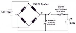
Here is your wiring diagram. The diodes will have a band on one end. That corosponds with the bands in the picture. The capacitor is optional. It is for smoothing out any ripples in the voltage. As Pete said, there are resistance calculators on the web. There is a link to one in the electronics section of the link pages that are in my signature. Usually a 1000 ohm resistor is a safe all-around value for mose aplications.

You only need one rectifier for all of your LEDs, although if you use more than 8 or 10 at the same time you probably should use heavier duty diodes.

Hope this helps.

Oops, a correction. The diodes should be 1N2222. Sorry about that. :eek:ops:
 

Attachments

  • bridge rectifier.jpg
    bridge rectifier.jpg
    10.8 KB · Views: 29

CN1

Active Member
May 6, 2003
1,059
0
36
Thank you all for the great info

Clark, excellent diagram and info. Thank you
 

CN1

Active Member
May 6, 2003
1,059
0
36
No it's 3 LED, 3 lights over 2 light (2 LED)

BTW I just did as instructed and it works!! Wonderfull. thank again