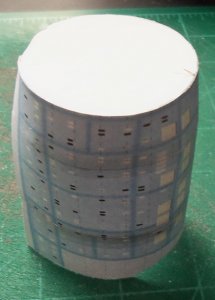
Again, I had to print several scales of the upper secondary hull piece to get one that fit right. Then, when it was curved it looked like the forward part was too wide. So I cut a section of the white area out and glued some 20 lb. bond paper strips colored with silver Sharpie to the edges as a tab area for the final top piece. I also printed several larger shuttlebay doors and picked one that left the least amount of gap at the top and edge glued them.
U.S.S. Enterprise NCC-1701-C
- Thread starter bgt01
- Start date
You are using an out of date browser. It may not display this or other websites correctly.
You should upgrade or use an alternative browser.
You should upgrade or use an alternative browser.
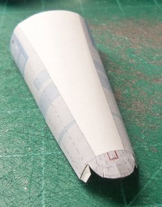
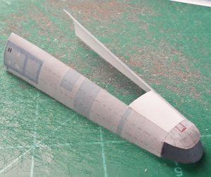
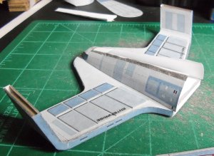
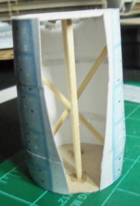
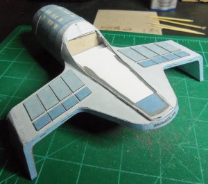
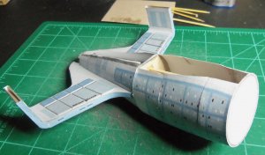
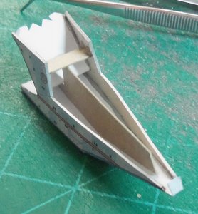
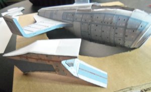
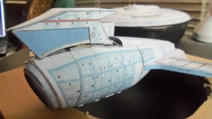
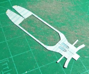
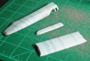
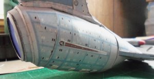
The forward section of the secondary hull also had to be rescaled to fit better. I curled it and glued it from behind with strips of bond paper. The white forward end piece was glued to 1mm chipboard for strength. For additional strength I printed another white rear end piece (same one that's on the other secondary hull part) and glued it the same way. This gave me a strong, stable section to attach the two hull sections. I added small strips of bond paper at the bottom of the hull so there would be more area to glue on the piece that covers it. I made some support pieces out of a craft stick and some BBQ skewers and super glued them in place.
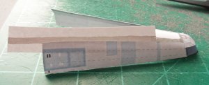
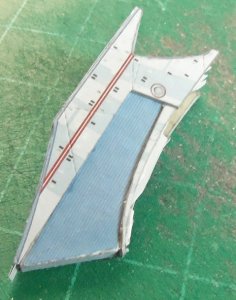
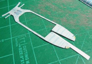
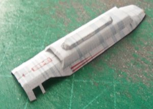
Once the two hull sections were glued together I saw the curved area didn't line up right. I cut some small pieces of hull scrap to full the holes that were going to be there. I added some more silver Sharpie colored bond paper along the edges at the bottom for more mounting area. These areas are super thin!. I had to reprint the bottom cover piece at several scales to get one that would work. The best one was going to leave more gaps where the curved end meets the hull. I glued the end off a rejected piece to cover the gap. I had to trim the sides on the final piece to get a good fit. Then I recessed the four small squares and the blue area for some detail and SLOWLY glued it in place. Then I checked my reference pics of the studio model and saw the blue area at the rear is RAISED! So I glued a duplicate blue area to 2 pieces of 1mm chipboard, edge colored it blue and glued it in place. It's a decent match for the model.
Once the two hull sections were glued together I saw the curved area didn't line up right. I cut some small pieces of hull scrap to full the holes that were going to be there. I added some more silver Sharpie colored bond paper along the edges at the bottom for more mounting area. These areas are super thin!. I had to reprint the bottom cover piece at several scales to get one that would work. The best one was going to leave more gaps where the curved end meets the hull. I glued the end off a rejected piece to cover the gap. I had to trim the sides on the final piece to get a good fit. Then I recessed the four small squares and the blue area for some detail and SLOWLY glued it in place. Then I checked my reference pics of the studio model and saw the blue area at the rear is RAISED! So I glued a duplicate blue area to 2 pieces of 1mm chipboard, edge colored it blue and glued it in place. It's a decent match for the model.
Attachments
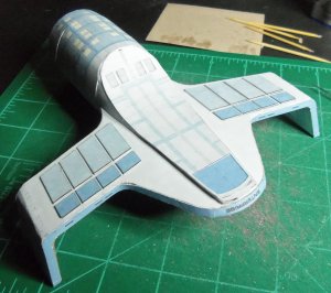
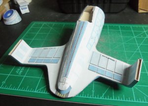
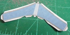
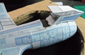
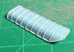
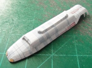
For more detail I added raised lifeboats like on the saucer. On this part there are fold lines going through the lifeboats, so I took the part into Photoshop and erased them for a cleaner look. Like before, I glued the part to 67lb. white cover, then trimmed and glued each piece. All were curved to varying degrees to mount flush with the hull.
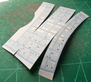
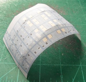
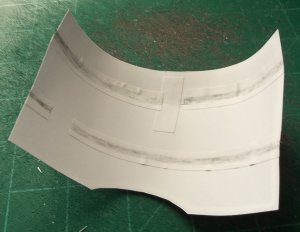
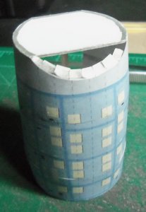
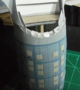
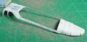
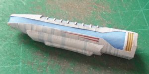
On the top section of the hull I added more edge colored bond paper for better gluing of the top piece. Like the others, the top piece of the hull had to be scaled several times for the best fit. The instructions show this piece being folded at several right angles so it has a jagged look. This does not match the studio model at all. The model has a smooth, curved shape like you'd expect a Starfleet ship to have. So, that's how I attached it. I'm not sure what this will mean, if anything, when it comes together with the dorsal.
On the top section of the hull I added more edge colored bond paper for better gluing of the top piece. Like the others, the top piece of the hull had to be scaled several times for the best fit. The instructions show this piece being folded at several right angles so it has a jagged look. This does not match the studio model at all. The model has a smooth, curved shape like you'd expect a Starfleet ship to have. So, that's how I attached it. I'm not sure what this will mean, if anything, when it comes together with the dorsal.
Attachments
NAVIGATIONAL DEFLECTOR
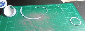
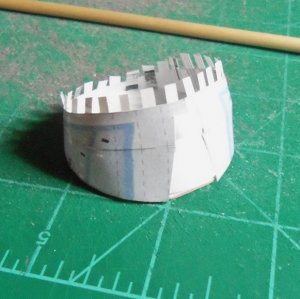
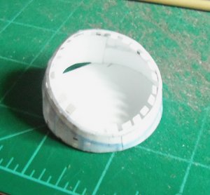
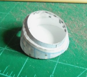
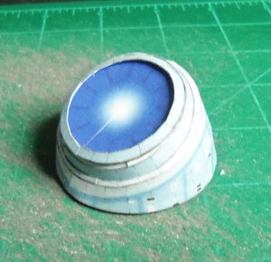
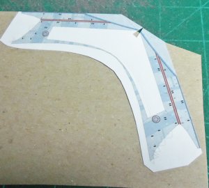
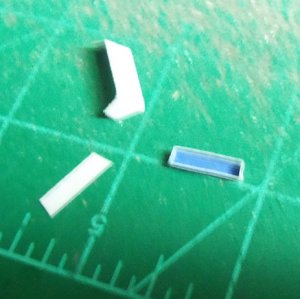
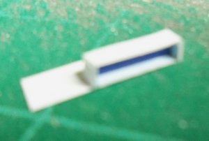
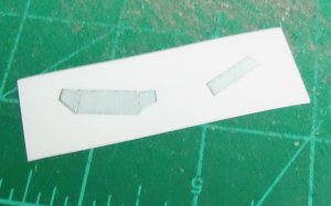
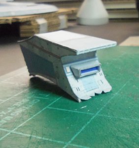
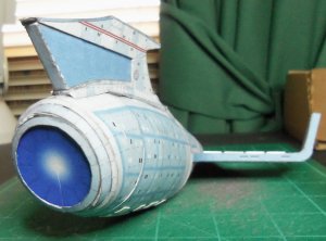
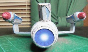
The Nav. Deflector housing also had to be rescaled to better fit my model. The two V-shaped cuts were glued from behind with bond paper. I made another 1mm thick version of the forward white support piece, since I knew it had to match this shape. The rescaled part was going to be wider than I needed, so I cut it in half and glued it to the white end, starting at the top on both sides and meeting at the bottom middle, then trimming the excess. As you can see, it's not perfect, but I can live with it.
As before, the four smaller strips that make up the front edge of the deflector had to be scaled up to better match the housing. The instructions aren't really clear about the assembly order of these parts, and it seems to only show three parts. I just laid them out and did what seemed "logical." Even scaled up, they are very small and hard to cut at the narrowest parts. I trimmed the outside edges with my precision scissors and did the insides with an fresh X-Acto blade.
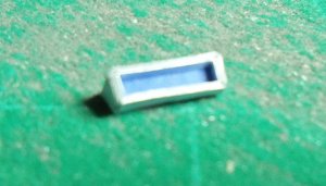
I glued small strips of bond paper around the inside to give the parts more area which to adhere. Starting at top center, I used weevers a straight metal pick to slowly glue the first strip around the edge. I used gel super glue and only glued about 1 cm. at a time. Using gel meant I only got one shot at positioning it right, but it also gave me a really strong hold on a very flimsy part. Any excess at bottom center got trimmed off. I repeated this for the outer blueish part of the housing and the last small edge piece.
The Nav. Deflector housing also had to be rescaled to better fit my model. The two V-shaped cuts were glued from behind with bond paper. I made another 1mm thick version of the forward white support piece, since I knew it had to match this shape. The rescaled part was going to be wider than I needed, so I cut it in half and glued it to the white end, starting at the top on both sides and meeting at the bottom middle, then trimming the excess. As you can see, it's not perfect, but I can live with it.
As before, the four smaller strips that make up the front edge of the deflector had to be scaled up to better match the housing. The instructions aren't really clear about the assembly order of these parts, and it seems to only show three parts. I just laid them out and did what seemed "logical." Even scaled up, they are very small and hard to cut at the narrowest parts. I trimmed the outside edges with my precision scissors and did the insides with an fresh X-Acto blade.
I glued small strips of bond paper around the inside to give the parts more area which to adhere. Starting at top center, I used weevers a straight metal pick to slowly glue the first strip around the edge. I used gel super glue and only glued about 1 cm. at a time. Using gel meant I only got one shot at positioning it right, but it also gave me a really strong hold on a very flimsy part. Any excess at bottom center got trimmed off. I repeated this for the outer blueish part of the housing and the last small edge piece.
Attachments
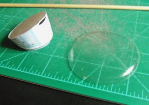
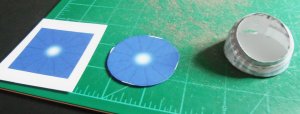
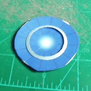
I tried building the original Nav. dish as designed, but it came out a disaster. It wasn't going to work with my rescaled parts and I wasn't going to get a good shape. Besides, to me it didn't look much like the one on the studio model. The new plan had me using a scrap piece of plastic as a backer. The plastic is from the packaging for a set of cheap tap lights. Next I designed new dish art with lines like the studio model. I trimmed a sliver out of the dish art so I could give it a slight curl. That made sure it would lay flat against the plastic. I colored the back of the outside trim piece with silver Sharpie, curled and glued it into a circle that matched the opening in the housing, and then edge glued it in position on the dish. I slowly trimmed the plastic to shape, then glued it into place. I like the final result, knowing how much worse it could have come out with me building it!
Attachments
NECK
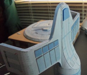
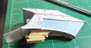
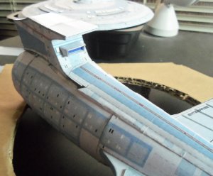
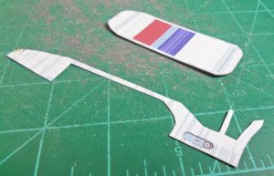
I actually built the neck twice. The first time was as the instructions said, but that had the blue area on the front sticking up about the curved blue line where it meets the saucer and there's no way that works. If the goal had been to build it that way and then push it into a cut out area of the saucer it would work, but the instructions don't say anything about that, I didn't see any obvious markings on the saucer for it, and I don't see how the top and back neck skin would to on. Having already built my saucer with the solid foam core middle, there's no way I'm going to try to cut a section out of it. So, I improvised.
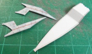
I glued the neck to 1mm chipboard for strength. I trimmed out the sides, cut off the narrow part at the bottom and cut off the blue areas at the top. I cut and trimmed the top and back neck skin and edge colored it with silver Sharpie. I slightly curved the sides as need and edge glued it to the skin. The chipboard gives a great surface for edge glueing. Since this neck is going to be supporting my heavy saucer, I stuck support pieces wherever I could. The parts are scrap and they are positioned wherever they seemed to make sense.
The blue section of the neck was glued to 67lb. white cover for strength and to better hold it's shape (no creasing or puckering). The small bottom piece I worked into place after glueing the blue section in place. This part doesn't look great because the chipboard was too thick, but I couldn't think of a better way to do it, and if I'd tried to assemble this with it still attached it would have been torn off immediately.
This build is very strong and stable. The curve where it goes against the saucer looks good, but there is a slight gap I'll have to somehow address.
I actually built the neck twice. The first time was as the instructions said, but that had the blue area on the front sticking up about the curved blue line where it meets the saucer and there's no way that works. If the goal had been to build it that way and then push it into a cut out area of the saucer it would work, but the instructions don't say anything about that, I didn't see any obvious markings on the saucer for it, and I don't see how the top and back neck skin would to on. Having already built my saucer with the solid foam core middle, there's no way I'm going to try to cut a section out of it. So, I improvised.
I glued the neck to 1mm chipboard for strength. I trimmed out the sides, cut off the narrow part at the bottom and cut off the blue areas at the top. I cut and trimmed the top and back neck skin and edge colored it with silver Sharpie. I slightly curved the sides as need and edge glued it to the skin. The chipboard gives a great surface for edge glueing. Since this neck is going to be supporting my heavy saucer, I stuck support pieces wherever I could. The parts are scrap and they are positioned wherever they seemed to make sense.
The blue section of the neck was glued to 67lb. white cover for strength and to better hold it's shape (no creasing or puckering). The small bottom piece I worked into place after glueing the blue section in place. This part doesn't look great because the chipboard was too thick, but I couldn't think of a better way to do it, and if I'd tried to assemble this with it still attached it would have been torn off immediately.
This build is very strong and stable. The curve where it goes against the saucer looks good, but there is a slight gap I'll have to somehow address.
Attachments
IMPULSE ENGINE
The impulse engine is designed to be scored and folded as one piece. I'm sure there is someone out there who could do this and make it look incredible. I am not that person. Again, time to improvise. I cut the part into three pieces: upper and side housing, lower housing and inside blue engine area. (Sorry about the blurry images, but the parts are too small for my camera to focus well)
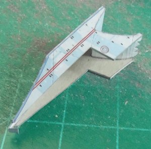
I glued the blue engine into its box shape, then glued several strips of card stock around the outside until it built up an edge that would match the inside area of the housing. I glued the housing pieces to scrap card stock, trimmed them to size and glued them around the blue engine box. I glued the engine in place on the neck and BAM!…a nice, detailed part. I also raised the yellow areas on the back of the neck with 67 lb. white cover. I'm not sure, but they look like lifeboats, so I made them look like the others.
The impulse engine is designed to be scored and folded as one piece. I'm sure there is someone out there who could do this and make it look incredible. I am not that person. Again, time to improvise. I cut the part into three pieces: upper and side housing, lower housing and inside blue engine area. (Sorry about the blurry images, but the parts are too small for my camera to focus well)
I glued the blue engine into its box shape, then glued several strips of card stock around the outside until it built up an edge that would match the inside area of the housing. I glued the housing pieces to scrap card stock, trimmed them to size and glued them around the blue engine box. I glued the engine in place on the neck and BAM!…a nice, detailed part. I also raised the yellow areas on the back of the neck with 67 lb. white cover. I'm not sure, but they look like lifeboats, so I made them look like the others.
Attachments
FINAL SECONDARY HULL
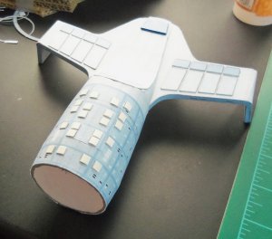
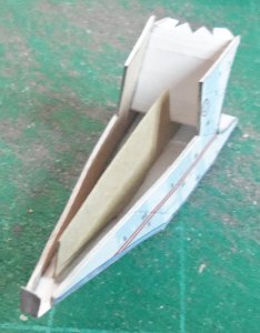
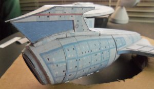
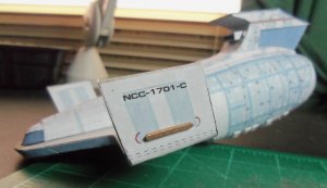
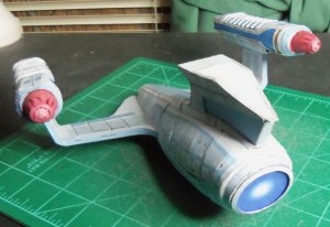
Due to the scaling issues, I am left with a secondary hull and neck that don't come together. Building a scaled up neck wouldn't work because it wouldn't fit the curve of the already constructed saucer. So, my solution was to do something they couldn't do on Gilligan's Island - plug the hole in the boat. I printed out another top hull piece that was scaled up enough to continue the blue section with the red stripes all the way to the neck. Then I cut it to a size that would cover the hole.
To further strengthen the neck, I cut pieces of craft sticks and glued them together so it would rest on the stick supports running through the secondary hull.
Attachments
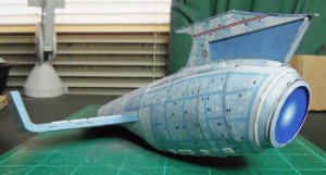
I placed the neck in final position and spot glued it in place at the very front only. Then I lined up my "patch piece" and glued it in place pressing up from the bottom with my metal pick, keeping the neck and back as straight as possible. Neither looks perfectly straight in relation to the hull, but they are acceptable for this build.
Attachments
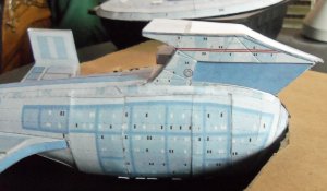
Next, I fashioned some side pieces out of hull scrap to cover the gaps at the base of the neck. I used the outside edges of extra top pieces of secondary hull (the same piece with the red stripe and blue area) and cut them to fit. I reversed the sides (glued left edge of top piece to right side of neck) to get a usable taper and to keep the hull patterns matched. I also added the raised nacelle phaser strips.
Attachments
WARP ENGINES
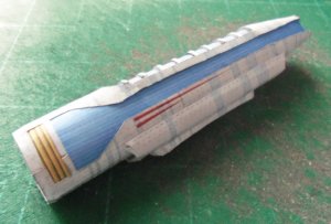
These engines are very rounded and sloped on the studio model, so I had a lot of misgivings that my meager skills could reproduce them in any way in paper. Because of that, this part of the build was painfully slow. To start, I had to figure out what the part with the red/light blue/dark blue square even was! It finally dawned on me it's the bottom of the ribbed part that sits in the middle of each engine. To reinforce that area (especially because that's where the narrow side strip glues to that you can see in pic 1) I glued it to 1mm chipboard and scored it where the ends raise up. I then scored and curved the blue ribbed top piece and glued it in place. I printed out another blue part and glued it to 67lb. white cover, cut out the white/gray ribbed areas, edge colored the sides with silver Sharpie and glued them on the original blue part for raised detail.
These engines are very rounded and sloped on the studio model, so I had a lot of misgivings that my meager skills could reproduce them in any way in paper. Because of that, this part of the build was painfully slow. To start, I had to figure out what the part with the red/light blue/dark blue square even was! It finally dawned on me it's the bottom of the ribbed part that sits in the middle of each engine. To reinforce that area (especially because that's where the narrow side strip glues to that you can see in pic 1) I glued it to 1mm chipboard and scored it where the ends raise up. I then scored and curved the blue ribbed top piece and glued it in place. I printed out another blue part and glued it to 67lb. white cover, cut out the white/gray ribbed areas, edge colored the sides with silver Sharpie and glued them on the original blue part for raised detail.
Attachments
I cut out the oval areas on top and glued copies of the ovals from below to give it a recessed look. I joined the two top halves by gluing a strip of bond paper at the join from behind. I did the same at the rear after notching and curving the pieces as needed. I colored both paper strips with silver Sharpie in case of gaps in the join, which I'm glad to say there were none. Then I used a wooden dowel to gently curve the part until I got it as close as possible to it's finished look. This is really hard because of the shape and I'd say my work is passable. Eventually you realize "that's as good as it gets" and you have to move on. To make it look a little better, I made some new reaction control thrusters (the little yellow rectangles on the ends) in Photoshop and glued them on. That area is slit and you can't get it to come together square, so this helped cover up that problem.
Attachments
Things seemed to be going OK, but trying to join the ribbed area to the top took care of that! The original ribbed part is out of scale with the rest of the housing. It's way too big and wide to fit that hole in the top! So, I reprinted it in several smaller scales until I got one that fit (settled on 90% of original) and built a new one. The final result wasn't too bad.
Attachments
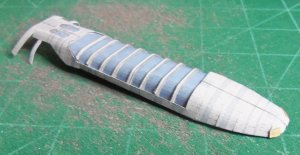
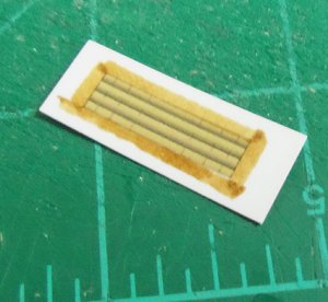
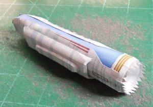
Next up was the warp grills. I gave a little edge color to the small gold grill (which looks like bamboo poles up close), trimmed, curved and glued into place. You have to go slow because of gluing to the small strip that separates the gold and blue grills.
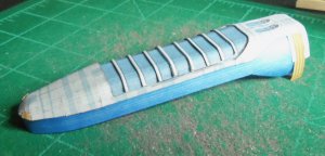
I didn't like the purple look of the original warp grill, so I altered it in Photoshop to look more like the blue color seen onscreen. I curved the wide ends at the front and glued them so just inside the edge. When I curved the grill around to the other side I discovered it's way too long! So I cut it at the middle rear. I worked my way around the top, glueing slowly in little dabs and doing my best to keep the thing straight. It is not possible to glue this part edge to edge with the top. If you try everything starts to twist. So, as usual, I compromised. The studio model's engines have a little lip that goes all the way around the grill and makes it recessed. That wouldn't work at the forward end, but as I got further back I just glued as close as I could to the edge while keeping the grill flat. That gave me a little overhang at the top rear and kept me from mangling everything. There's not a lot of are to glue to, so once I had it where I wanted it I spread some brush on super glue from behind to weld it in place.
I repeated this for the other side. At the rear, I carefully trimmed each piece a little at a time until I had it where they would edge join. I glued a scrap piece of the grill behind the edge join to help hide the seam.
Attachments
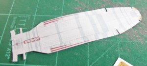
The bottom on the housing is similar to the top except no recessed parts and no hole in the center. So it went together in the same fashion. I cut, curved and assembled the two areas of the housing where the pylon attaches, and quickly found out this part is also out of scale. It's too big. You can tell right away because the blue hull lines don't match up. Again, I printed some new parts at different scales until I got one that fit.
Next was a lot of dry fitting and slow gluing to join the two halves. I used a wooden dowel through the open end to give myself something to press against as I worked my way around.
Next was a lot of dry fitting and slow gluing to join the two halves. I used a wooden dowel through the open end to give myself something to press against as I worked my way around.
Attachments
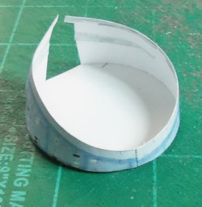
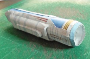
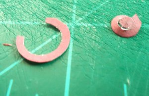
This was my least favorite bussard collector of all time, and I don't like making any of them so that's saying a lot! There's no "base" for this part and it's also out of scale with the housing, so I had to make it up some. I glued bond paper tabs colored with silver Sharpie around the inside edge, curled and glued the blue housing strip, and cut off the excess at the bottom. I glued the red and blue base part to 1mm cardboard for some stability. I had to trim it to get it to fit, and it doesn't look great. It was trial and error.
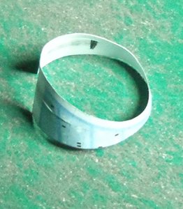
The collector end is designed as one curled part, which I can't make. So, I cut the bottom part of the ring off, curled the top part, and glued it back together. The rest of the collector is one part that you have to slit, curl and fold to make it come together and it is terrible! If I could have found any kind of domed substitute I would have. Like the other parts, this one is out of scale and too big. So, I started from top center and curled it until I got the shape I needed, cut off the excess and glued it in place. I cut some tiny strips of bond paper, colored them and glued them in the end to give the end cap something to hold on to. A last bit of glueing and I had what looked more like an angry lipstick than a bussard collector! Now I have to do it all again for the other engine!
The collector end is designed as one curled part, which I can't make. So, I cut the bottom part of the ring off, curled the top part, and glued it back together. The rest of the collector is one part that you have to slit, curl and fold to make it come together and it is terrible! If I could have found any kind of domed substitute I would have. Like the other parts, this one is out of scale and too big. So, I started from top center and curled it until I got the shape I needed, cut off the excess and glued it in place. I cut some tiny strips of bond paper, colored them and glued them in the end to give the end cap something to hold on to. A last bit of glueing and I had what looked more like an angry lipstick than a bussard collector! Now I have to do it all again for the other engine!
Attachments
DECALS
I knew when I started this model that because the areas where the hull markings are on the warp engines and secondary hull have to be slit and folded and glued together, there was no way those marks were going to be straight or legible. So, I decided to make decals, which I've never done before. I redid the markings in Illustrator and adjusted them as needed based on screen caps from TrekCore.com. I printed them on clear sticker paper I got at Hobby Lobby. They trimmed out well, but the paper wasn't as "clear" as it looks on the package. You can definitely tell it's a sticker. And, the paper says it's "repositionable", which means it really won't stick to anything! So, I got the stickers in place and then glued them down with a very thin coat of regular gel craft glue. The models surface isn't completely smooth, particularly on the engines, so they look a little wavy. But, they are completely legible, and that's what was most important to me. And they still look better than what was printed on the model. But, I'm going to have to find a better sticker paper for future models.
I knew when I started this model that because the areas where the hull markings are on the warp engines and secondary hull have to be slit and folded and glued together, there was no way those marks were going to be straight or legible. So, I decided to make decals, which I've never done before. I redid the markings in Illustrator and adjusted them as needed based on screen caps from TrekCore.com. I printed them on clear sticker paper I got at Hobby Lobby. They trimmed out well, but the paper wasn't as "clear" as it looks on the package. You can definitely tell it's a sticker. And, the paper says it's "repositionable", which means it really won't stick to anything! So, I got the stickers in place and then glued them down with a very thin coat of regular gel craft glue. The models surface isn't completely smooth, particularly on the engines, so they look a little wavy. But, they are completely legible, and that's what was most important to me. And they still look better than what was printed on the model. But, I'm going to have to find a better sticker paper for future models.
Attachments
WARP ENGINES FINAL
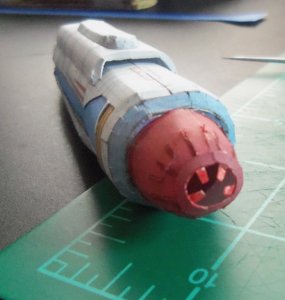
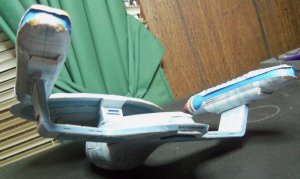
Both engines are now finished and installed. The second engine doesn't look as good as the first. I rushed a little on it due to a false sense of security. I keep telling myself it could have been a lot worse. I lightly glued both with regular gel glue so I could adjust for straightness and level. Then, I put some brush on super glue around the bases to lock them into place. Looks like an emergency saucer separation now!
Both engines are now finished and installed. The second engine doesn't look as good as the first. I rushed a little on it due to a false sense of security. I keep telling myself it could have been a lot worse. I lightly glued both with regular gel glue so I could adjust for straightness and level. Then, I put some brush on super glue around the bases to lock them into place. Looks like an emergency saucer separation now!
Attachments
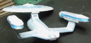
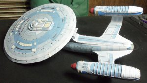
FINAL NO LIGHTS
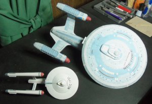
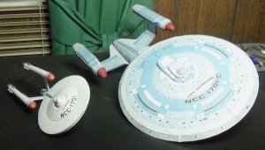
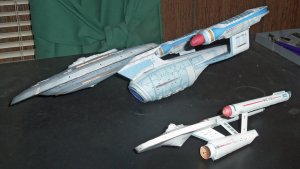
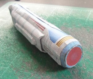
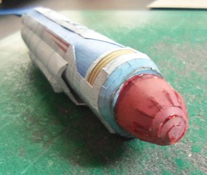
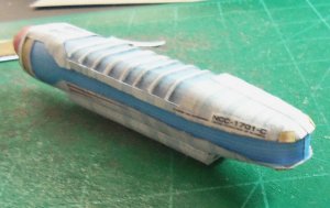
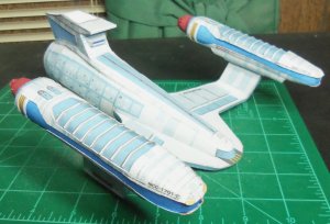
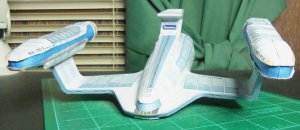
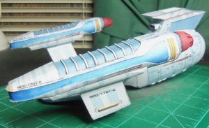
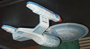
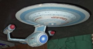
Well, here she is. The U.S.S. Enterprise NCC-1701-C.
This is actually near final configuration because I still have to add the running lights. For me, I'd say this an above average build. I've put the most thought and time into this model than any I've built to this point and I'm pleased enough how it came out. The scaling issues really changed how the final product looks compared to the studio model - the engines are now too short, the bussard collectors aren't domes, the secondary hull is too long and the saucer is too small. Rescaling a lot of parts let me finish this model, which was my ultimate goal, in a way that isn't screen accurate, but also isn't so bad that it looks ridiculous (unless you think the Ambassador design is ridiculous to start with, then I can't help you). If I didn't have the programs and ability to manipulate these parts, she would have been sent to the scrapyard a long time ago. However, like the illustrious Captain Kirk (sarcasm implied!), I figured out how to change the rules and came away with a nice model to add to the fleet that is rapidly taking over my bookcase.
Gratuitous beauty shot at no extra charge! Now, on to the Enterprise-D!
Attachments
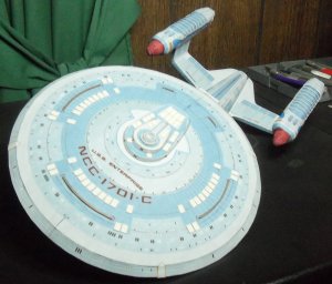

1701 AND 1701-C
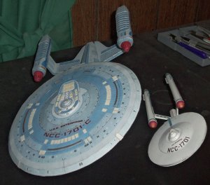
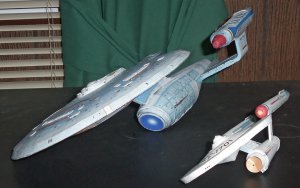
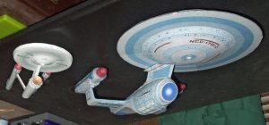
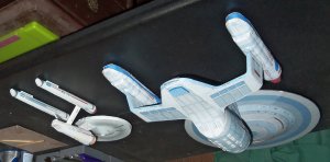
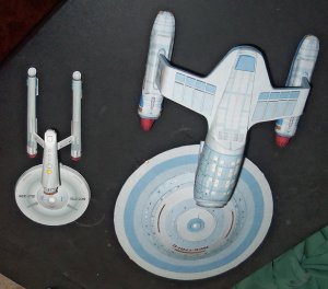
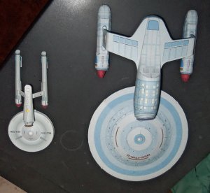
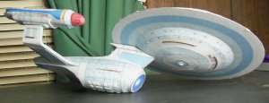
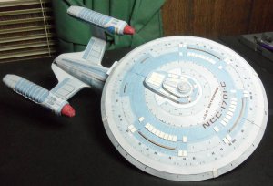
I wanted an Enterprise-C in scale with my Rawan TOS Enterprise, and I think I did OK. Here are the two grand ladies together.
Now it's time for the Trekkie side of me to throw out some thoughts on this ship that have been rattling around through the build.
1. How could a group of model builders as dedicated at the ones that worked on Star Trek build an "Enterprise" and not notice she had no fore or aft torpedo launchers? This equipment is firmly established as standard on starships post-TOS.
2. By relocating the impulse engine to the neck the saucer would have no way to move after a saucer separation except for the RCS thrusters. This is a serious compromise for crew survivability due to limited fuel and maneuverability. Someone could retcon an answer and say there are impulse engines in the saucer that are only visible after separation, but that would mean those engines could never be test fired until an actual emergency. That would be inefficient and foolhardy. The Enterprise-D has the main impulse engine in the neck but the saucer has independent impulse engines to account for the move.
3. Why doesn't the Enterprise-C have a ventral phaser array like all the Enterprises before and after it! This is serious gunnery blindspot. Again, all the model makers had to do was look at the Enterprise-D to see it!
4. We saw the Enterprise-C one time, same as the Enterprise-B. It makes me think about the untapped wealth of stories Paramount could still be telling about the Star Trek prime universe. To think there are two ships named "Enterprise" that we know next to nothing about is amazing. It's the same feeling I get thinking about "Star Trek: Enterprise." There were hundreds of elements barely touched on in TOS that would have made great stores for a prequel TV show. There were 12-14 other Constitution class ships, ships we've barely or never seen, whose adventures could have been just as entertaining to watch. That's a big reason why I keep coming back to this franchise, because there's so much still to learn.