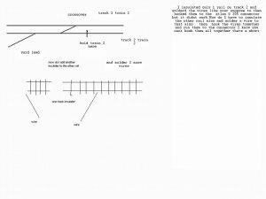
Me again doing a cross over from what I call track 1 to track 2. I Insulated one rail and solderd the wires to the rails before and after the Insulater .Got a #205 atlas connector and wire it up but when i tested it the train didnt stop. Was i suppose to Insulate both rails and wire both rails.I did this years ago but ill be #$%^ if I can remember how I did it.Try to explain it better train 1 crosses over to track 2 for a short distants to go into the yard as train 2 holds short of the crossover.Yes i need to buy a wiring book any help thank you
track Insulating
- Thread starter erie
- Start date
You are using an out of date browser. It may not display this or other websites correctly.
You should upgrade or use an alternative browser.
You should upgrade or use an alternative browser.
A diagram would help understand what you tried to do. If you can come up with something that shows how the tracks are laid out, and where you put the insulated joiner, we'd be able to better help you out.
Without seeing it, it sounds like the track on the other side of your insulated joiner is getting power from somewhere else. Do you have feeders in there? Is it connected to another part of the layout?
Without seeing it, it sounds like the track on the other side of your insulated joiner is getting power from somewhere else. Do you have feeders in there? Is it connected to another part of the layout?
ok heres a shot correct me if im wrong but you insulated one rail and then you solderd a jumper wire from one rail to the other side of insulator? if thats the case you just continued the power despite the insulator. to me it also sounds as if you want the train to cross from track one over to track 2 and have track 2 on its own power supply to be able to pass perhaps a 2nd train.
It's going to depend on where track 2 is getting its power from. Where does it go to the right of your diagram?
If it doesn't have any feeder wires connected to it, or it's not connected to any other part of the layout, then what you have done should work.
That it's not working suggests you've got power feeding track 2 from somewhere else.
If it doesn't have any feeder wires connected to it, or it's not connected to any other part of the layout, then what you have done should work.
That it's not working suggests you've got power feeding track 2 from somewhere else.
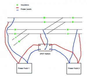
I'm going to assume that both Tracks 1 and 2 continue to the right a bit and there are other feeders on those tracks. In order to do what you have stated you would want to create a section of track that is isolated on both ends, something that would be longer than the longest engine length you would plan to run. Then you would hook up a feeder from this isolated section to the switch and another wire from a powered section to the switch. That way when the switch is in the off position any train coming down track 2 will drop when the engine(s) lose power, and you can flip the switch to get it moving again once the train from track 1 has crossed. I can try and post a diagram of my thoughts later tonight.
Rob
Rob
Hi...I presume you're not using DCC...For DC, you need to break up your layout into sections (called "blocks"). You will also need two power packs (minimum). Each block should be wired to a DPDT switch that lets you choose which section of track will be powered with one of the two power packs. That way you can stop your engine short of the crossover (not have it come to a screeching halt by turning its power off). Depending on the type of turnouts you are using, you will need to place insulating joiners on BOTH tracks that make the crossover, and have the crossover and a length on each side, powered by one of the two packs, as well as the approaching track and the track leading into the yard.
Not easy to describe....Do get a wiring manual...It'll make your life alot easier....
Not easy to describe....Do get a wiring manual...It'll make your life alot easier....
i agree on the block idea if your not doing dcc but i lack more the what is basic on that so ill let these guys take that on. good luck.:thumb: