Tis the season for "Do-Overs"

Will_annand

Active Member
Jan 12, 2004
1,464
0
36
69
Huntsville, Ontario
www.muskokacomputes.com
Like 3 phase, I want a "do-over", no, not a tray of those little bit size foods...

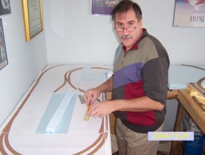
I was not happy with the way things were looking on two of my modules, so I went to the local "Home Building Centre" (no not that big Depot place) and picked up four 2'x4' pieces of 2" thick blue styrofoam.

I have pulled out the subroadbed and corking on the two modules (Cheltenham/Sligo and Forks Of The Credit). Waiting for the glue to dry on the foam right now.

I have a question though....

I have several pieces of cork glued to particle board shelving. What is the best way to get it off and reuse it?

Forgot to mention, the track plan will stay the sme, just changing what is goes on. :D
 
C

Catt

Will,what is the roadbed glued down with? Is it plain old white glue (Elmer's)?

If it is just soak it down with water,preferbly warm and let it set for a spell then work a putty knife under it and start prying up carefully.
 

MasonJar

It's not rocket surgery
Oct 31, 2002
5,362
0
36
Ottawa, Canada
Visit site
Hi Will,

Hope things are well on the CVR...!

When you reinstall your cork (and your track for that matter) you might try adhesive caulking. It can be taken apart easily with a putty knife, but holds well, and even flexes if your layout is subject to weather (although not likely in the living room... ;) ). You can even get it in a pressurized can, so you don't need a caulking gun. Just use a notched trowel to spread it - like putting down tile - and a little goes a long way... Be sure to get foam friendly - I used latex, which is also paintable.

Andrew
 

joe ramirez

New Member
Nov 26, 2004
32
0
6
48
"that foam bedding i tried to use"

I used the foam bed because it was easly bent into shape. That was my main reason over cork. I also had a transition from Bachman snaptrack to flex and the foam fit nice. I also did not glue it down just nailed the track and the bed right to the ply.
3phase, what problem did you run into
confused.gif

Joe in houston
 

Will_annand

Active Member
Jan 12, 2004
1,464
0
36
69
Huntsville, Ontario
www.muskokacomputes.com
Andrew, things are moving slowly on the CVR, I did place some layout photos on my website last month.

Three modules are corked and ready for track. If you check out the photos, it is the Cheltenham, Sligo and Forks modules that are being "blue foamed".

I will have time between Christmas and New Years to work on the layout.

As to the Adhesive caulking, "Now You tell me!!"
I have three large bottles of White Glue sitting here. :D

3phase, which type of foam did you use?
I have read many reports to stay away from the white foam.

They say the foam is easier to shape, and as my railroad follows the course of a river, I needed the elevation above the water at places, it should be easier to trim the foam instead of the plaster.
 

Will_annand

Active Member
Jan 12, 2004
1,464
0
36
69
Huntsville, Ontario
www.muskokacomputes.com
What do you know, I did have time to work on my layout yesterday. My Uncle came over for dinner and we both did some work on the layout. I even have proof. He snapped this candid shot, I did not even know he had the camera out. :D

Andrew, note the paper layout plans on Module 01, I printed them full size from Atlas RTS. As of this writing, the paper has been replaced by cork roadbed.

The mainline on the left of the shot will start to drop in elevation just above the turnout, it will slowly drop to bench level and run along the rear of the layout, not tunnel, but a semi hidden return. Disappear into the trees as it were.
 

Attachments

  • Will and The CVR.jpg
    Will and The CVR.jpg
    46.4 KB · Views: 296

Will_annand

Active Member
Jan 12, 2004
1,464
0
36
69
Huntsville, Ontario
www.muskokacomputes.com
A couple of friends from the local club came up to see my layout on Boxing Day.
I thought they came to answer a few of my questions. Ed, however, had other plans....

He and Danny wanted to work. They started by showing me how to smooth the cork so that the tracks could lay and run smoothly. Then started to lay track and how to solder the wires to the rail joiners so when laid, there are no solder joints visible.

As of right now, I can run the train from the crossover south of Cataract, through Cataract to the end of the center module. On both the main line and passing track.

I have a list of a couple of things I need to buy to aid in the wiring of the layout.

Ed and Danny told me of an easy way to work the control panel, using a sheet of pegboard. You draw out the track plan on the pegboard, then use nuts and bolts in the holes along the track lines where you want to include power blocks. Then you wire up a "Wand" similar to a pencil soldering iron. But when you use the wand and touch a screw head, it toggles the power. The same can be done for the powered switches I have. No need for several toggle switches, just bolts and nuts.
 

Will_annand

Active Member
Jan 12, 2004
1,464
0
36
69
Huntsville, Ontario
www.muskokacomputes.com
I have not seen it myself, he said when it came time for me to make one I should go down and visit Ed's layout.

The way Danny described it, you take a pegboard and paint your track plan on it.
Then you use bolts for each turnout or block, he suggested different styles of bolts for each. Then you take what looks like a pencil soldering iron. You touch the bolt head of the block or turnout and it toggles the switch left or right. Or if it is a block you are touching, it toggles the block off or on.

Val, you have Ed's email, he is the fellow who runs the Muskoka Model Train Show.
BTW, will you be making an appearance next summer with your modules?
You should bring up Mr. Matthyro as well.
 

SD90

Active Member
May 23, 2003
789
0
36
Canada
Visit site
I just ordered 6 dozen Long radius Peco switches and another case of flex track. I think that should be enough to almost finish the layout.
 

docsnavely

Member
Sep 20, 2004
109
0
16
42
Zushi, Japan
I think I understand the whole idea of the pegboard. SOMEONE PLEASE CORRECT ME IF I AM WRONG!:D

Each individual bolt is to replace the actual switch for your turnouts. Each bolt is wired to each individual switch along with either track power or an independent supply of some sort. You then tap the bolt of your choice to throw a switch. The wand is in essence a ground. That way when you tap the bolt with the wand you are closing the circuit.

Hope this makes sense to someone other than me!:rolleyes: :D

-doc