

My concern is if I laminate it, at the end will everything fit together? I say it because in the Enterprise Build I almost had a problem like that, after laminating some formers... But in the end, everything went well.
The UHU02 Colonial Viper appreciation thread
- Thread starter Revell-Fan
- Start date
You are using an out of date browser. It may not display this or other websites correctly.
You should upgrade or use an alternative browser.
You should upgrade or use an alternative browser.
Mine is just laminated to its counterpart, but, I did use 200gsm stock instead of 160gsm.
But, even at my early stage in the build, I am wondering if any extra reinforcement is actually neccessary, because as the model goes together, everything 'rigidifies' as each piece is added.
But, even at my early stage in the build, I am wondering if any extra reinforcement is actually neccessary, because as the model goes together, everything 'rigidifies' as each piece is added.
Are you using 200gsm for the whole model, or only in the "tree" part? All right, I'll blow it: I intend to buy some paper, and print it TODAY. Maybe even start at it tonight, after hours.
Are you using 200gsm for the whole model, or only in the "tree" part? All right, I'll blow it: I intend to buy some paper, and print it TODAY. Maybe even start at it tonight, after hours.
I am only using 200gsm for the main frame and the bulkheads. The rest is all out of 160gsm.
Ok, I did also print the model out on 80gsm too, as a thinner paper should make a cleaner and neater piece when making all the really tiny pieces.
Looking forward to you build pics, Rogerio.
Take your time and good luck!!!:thumb:
P.S: Make sure you have a really good magnifying glass .....sign1
Take your time and good luck!!!:thumb:
P.S: Make sure you have a really good magnifying glass .....sign1
Silveroxides Viper
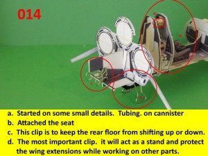
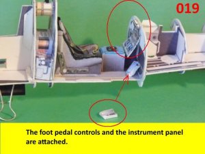
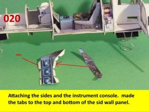
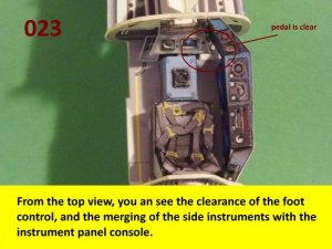
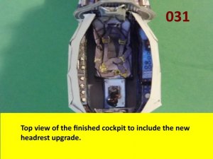
Started on the cockpit construction. one of the most important tools to help in the construction, are the butterfly clips. If you are going to handle the ship constantly, it will prove indispensable. Those prongs sticking out are prone to being bent out of shape and the clips will act as a stand to balance the frame while working on it. The foot pedals are trimmed and they will present a problem later on when attaching the sides. I compensated for this but that portion will come later when the side panels are adjusted to fit around the pedals. See you all soon with more updates.
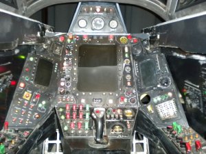
Keep up the good work guys, I am depending on your expertise in finding the faults. There are a few in the cockpit and I will comment later on them, The instrumentation is not complete and that upper instrument panel is suppose to rise higher. That missing hump on the top of the forward is an extension of that part. That is were I noticed the missing hump. I built a Viper a while back and that portion was my indicator as to where to place the HUD.
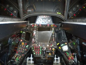
In my reference file, there are three versions of the cockpit. the early version did not have that video communicator in the lower right of the panel. In its place, it was a clip section for the pre-flight checklist. The upper instrumentation later on, had a HUD (heads up display) system instead of instruments. Other stuff will pop up now and then, especially in the cockpit section. i will point some more out later on. Over all, the cockpit still looks great as is. Enjoy and see you all with more postings,:thumb:
Started on the cockpit construction. one of the most important tools to help in the construction, are the butterfly clips. If you are going to handle the ship constantly, it will prove indispensable. Those prongs sticking out are prone to being bent out of shape and the clips will act as a stand to balance the frame while working on it. The foot pedals are trimmed and they will present a problem later on when attaching the sides. I compensated for this but that portion will come later when the side panels are adjusted to fit around the pedals. See you all soon with more updates.
Keep up the good work guys, I am depending on your expertise in finding the faults. There are a few in the cockpit and I will comment later on them, The instrumentation is not complete and that upper instrument panel is suppose to rise higher. That missing hump on the top of the forward is an extension of that part. That is were I noticed the missing hump. I built a Viper a while back and that portion was my indicator as to where to place the HUD.
In my reference file, there are three versions of the cockpit. the early version did not have that video communicator in the lower right of the panel. In its place, it was a clip section for the pre-flight checklist. The upper instrumentation later on, had a HUD (heads up display) system instead of instruments. Other stuff will pop up now and then, especially in the cockpit section. i will point some more out later on. Over all, the cockpit still looks great as is. Enjoy and see you all with more postings,:thumb:
Attachments

Silveroxides Viper
As for cockpits and instruments. I am glad to work with this one, It could have been the third and last version in "Hero" and the last episode that Apollo flew his Viper.:thumb:
As for cockpits and instruments. I am glad to work with this one, It could have been the third and last version in "Hero" and the last episode that Apollo flew his Viper.:thumb:
Attachments
Silveroxides Viper
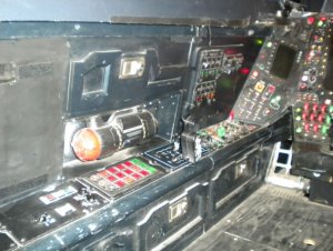
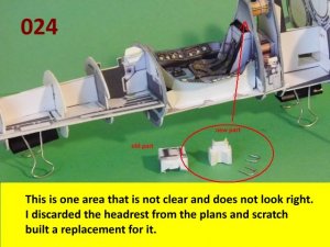
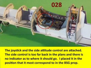
More work on the cockpit. The side wall and instrumentation is off. The side instrument panel is supposed to have a sharp downward angle on both side. In this version, the instrument panel from front to rear is almost even or horizontal. The attitude control on the left does not have visible attaching point. In one version of the instrument panel, there are three gauges between the joystick and the bottom of the instrument panel. In another version, it is missing but that is the one with the checklist clip instead of the video communicator. But as I have mentioned before, I still like the layout. In the side consoles, first pic, you can make out the recessed instrument. The buttons and warning lights are also raised by using the glue rivet technique. I placed three coverings of glue and they did raised the lights some. Enjoy and I will be back soon with more updates.:thumb:
More work on the cockpit. The side wall and instrumentation is off. The side instrument panel is supposed to have a sharp downward angle on both side. In this version, the instrument panel from front to rear is almost even or horizontal. The attitude control on the left does not have visible attaching point. In one version of the instrument panel, there are three gauges between the joystick and the bottom of the instrument panel. In another version, it is missing but that is the one with the checklist clip instead of the video communicator. But as I have mentioned before, I still like the layout. In the side consoles, first pic, you can make out the recessed instrument. The buttons and warning lights are also raised by using the glue rivet technique. I placed three coverings of glue and they did raised the lights some. Enjoy and I will be back soon with more updates.:thumb:
Attachments
Another mirroring error.
Part 175 has a mirroring error aswell. Ok the print is sooooo tiny at 1/50, it is difficult to read anyway. Just thought those of you that are upscaling, may see it better ......

Part 175 has a mirroring error aswell. Ok the print is sooooo tiny at 1/50, it is difficult to read anyway. Just thought those of you that are upscaling, may see it better ......
silveroxides Viper
Thanks for looking in on my version of the build guys. And thanks Dan for your input, I will see if it hampers my build or I may leave it alone.
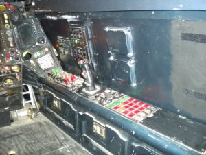
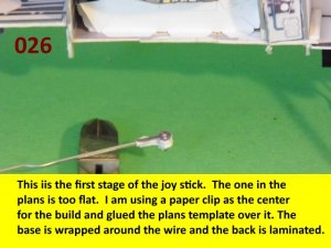
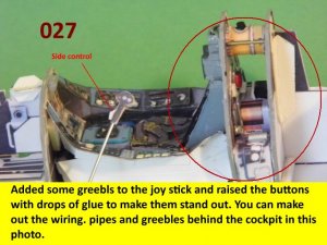
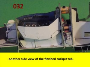
More on the cockpit. The joystick was a little too flat. Using a paper clip wire, I cut the part with an extension on the base. I wrapped the extended part around the base and built up the head piece.
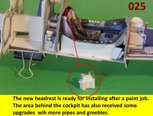
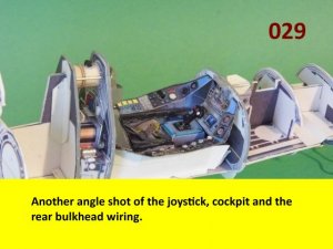
The side attitude adjuster is made from a straight pin and a thin strip is rolled around the handle. The tub is closed up and you can make out some greebles,wiring and panels in some of the photos. Enjoy and be back soon with more. On a different note, I may post a little slow while I try to clean up my system. It ha been locking up on me lately.:thumb:
Thanks for looking in on my version of the build guys. And thanks Dan for your input, I will see if it hampers my build or I may leave it alone.
More on the cockpit. The joystick was a little too flat. Using a paper clip wire, I cut the part with an extension on the base. I wrapped the extended part around the base and built up the head piece.
The side attitude adjuster is made from a straight pin and a thin strip is rolled around the handle. The tub is closed up and you can make out some greebles,wiring and panels in some of the photos. Enjoy and be back soon with more. On a different note, I may post a little slow while I try to clean up my system. It ha been locking up on me lately.:thumb:
Attachments
Awesome as usual, Silveroxide. No matter how used I get to the quality of your builds, you can always surprise and astound me. WAY TO GO!
@Silveroxide: Your build of the cockpit looks simply AMAZING! All of the detail that you are putting into it is really making this model come to life!
If I may make a note, It was pointed out to me that the upper side panels are suppose to be attached to the inside of the skin for the cockpit section. Please see attached pic.

If I may make a note, It was pointed out to me that the upper side panels are suppose to be attached to the inside of the skin for the cockpit section. Please see attached pic.
If I may make a note, It was pointed out to me that the upper side panels are suppose to be attached to the inside of the skin for the cockpit section. Please see attached pic.
View attachment 120755
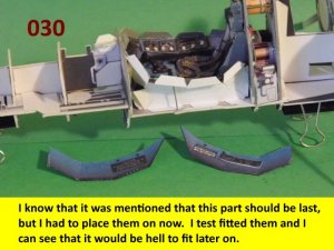
Keep in mind, that to place the skin over cockpit, you have to place it over the cockpit side ways. When you turn it to align it with the cockpit, the side panels may catch and cause damage to the cockpit walls. That is my reasoning for placing the side wall panels on when constructing the cockpit. There is very little space tolerance when applying the skin on this model.wall1
Keep in mind, that to place the skin over cockpit, you have to place it over the cockpit side ways. When you turn it to align it with the cockpit, the side panels may catch and cause damage to the cockpit walls. That is my reasoning for placing the side wall panels on when constructing the cockpit. There is very little space tolerance when applying the skin on this model.wall1
VERY GOOD POINT!:thumb:
I have not thought of that!wall1
Maybe the issue as outlined, is a 'Catch 22'.........
On the side wall, or as part of the cockpit tub, surely the problem would be the same..........Also, the cockpit is gonna look rather weird when the model is de-skinned if the side panels are attached to the cockpit tub rather than the body shell...........
Either way, these 'annoying' side panels could be soaked in ca glue to strengthen them, especially the edges, against the (possible) damage caused by the constant removal and replacing of the outer skin......
Just my Euro's worth........
More on those panels and hopefully the first one to get there will let us know how it comes out.
Option 1. If it is to be displayed naked, then there is nothing to worry, leave as is.
Option 2. If you are going to handle it and show off how it goes together, then wait forr the first one to get there to find out if it is feasible with the panels attached to the skin.
Option3. It is to be displayed semi skinned, with portions showing, then leave the skin over the cockpit alone and it should work out.
Option 4. If it is to be fully skinned, then there is no need to worry except for the sliding canopy.??????? (It is possible but you need that fuselage hump on the top)
Regardless, it should be interesting.