Switch Stand location

Gary S.

Senior Member
Oct 13, 2005
1,576
0
36
Texas
My turn-outs are controlled by under-the-layout throw rods. I am going to put Central Valley non-operating switch stands at each turn-out. I will simply add a small piece of cork to the existing roadbed, add some extended ties out onto this, ballast it along with the rest ofthe track, then mount the switch stand on the extended ties.

Question 1: Is there a standard distance from the centerline of the track that switch stands are placed?

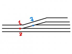
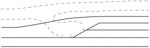
Question 2: Say we have a turn-out that is between other tracks, with a clearance from center to center of 14 scale feet. In other words, the turn-out is sandwiched between other tracks. Where would the switch stand go? Would the real railroads use some kind of low-profile stand? Or, is there enough room for a regular switchstand? Or would they use some extra-long throw rod to extend the switch stand outside of the other tracks?
 

Russ Bellinis

Active Member
Feb 13, 2003
4,501
0
36
78
Lakewood, Ca.
Visit site
I think when you speak of a "switch stand" you are talking of a manual control where a switchman would operate the switch to put the train into a siding. This is opposed to a ctc controlled switch that is operated by a traffic controller in a centralised location-ie Cajon Pass on the BNSF is controlled from Kansas. In the case of manual switch stands, the rule of thumb to remember is that the railroad would always put the stand in a place where the switchman would be out of harm's way when switching the train. In other words he would never be in a position to be hit by a train on a neighboring track while working the switch. Safety first is not only the way modern railroads work, but is also federal law.

To answer your first question. I'm not sure of a standard distance, but when I was working on a refrigeration unit on a U.P. car at the City of Industry yard, I noticed that even though the switches were controlled by the central tower, there were some that didn't work and had to be thrown by hand. If I remember correctly, those switches that had to be thrown by hand had their switch controls run underground to the side of the ladder so that no trainman had to step over a track to work the manual controls even for a switch that was 2 or 3 tracks over.
 

Gary S.

Senior Member
Oct 13, 2005
1,576
0
36
Texas
Okay, revisited, with a diagram:

russ, yes, I am speaking of the apparatus that a switchman would use to manually throw a switch on the prototype.

Looking at the following diagram, the red dot and blue dot are the turnout points. Where might the switch stands be located? The rods would be routed under the adjacent tracks? The red points may be controlled from location 1 or 2, and the blue from 3?
 

Attachments

  • tr.jpg
    tr.jpg
    14.4 KB · Views: 4

60103

Pooh Bah
Mar 25, 2002
4,754
0
36
Brampton, Ontario, Canada
Visit site
Gary: I've never seen a setup just like that one with sidings in the middle.
I would expect the railroad to put both switchstands on the north (upper) side of the tracks but to swing the single north track around them.
You don't really want Brakie dropping off his car and running across a set of rails to throw the switch. And both stands should be positioned so that noone has to cross the tracks to go from one stand to the other. (an exception would be if the was another siding coming on the south side.)
 

MadHatter

Charging at full tilt.
Jan 27, 2007
1,034
2
36
37
Centurion, South Africa
Hi Gary S.

For everything that happens on a real railroad there is always a counterpart on our models.

Answer to Question1: (These are only theories)

There is probably a standard distance from track center to the actual machine (or rather mechanism). The first reason that comes to mind is that there is a certain geometry to be kept in mind when they lay the point and mechanism. On our layouts when we place working ground throws we place the point blades and mechanism in the center and then fasten everything together.

The second reason is the fact that the items were/ are made on some sort of a production line so are made to a standard.

Answer to Question2: On our model railroads sometimes we need to compromise because of space or what have you. Locally I've seen that when there is a lot of track work they put the point throws- in our terminology point tumbler- on the outside of all the tracks (Double slip crossovers between two parallel tracks come to mind).

So, while my conclusion is that there is a standard, there needs to be compromises sometimes. I'm sure that the guys in the workshops get upset if they have to do extra work though by making a special throw- bar. :mrgreen:
 

Gary S.

Senior Member
Oct 13, 2005
1,576
0
36
Texas
I just noticed in the "Canadian or Canadien" thread.... photos of the prototype boxcar... the switchstand is in between the tracks which are on relatively close centers. So I could do that too. HO scale, track on 2" centers, switchstand between tracks?
 
Jan 12, 2006
231
0
16
43
Southern CA
I don't have the issue in front of me, but the November '07 (most recent) issue of Model Railroader has part one of an article by Paul Dolkos on detailing the right of way, and there is a chart with standard distances for lineside items, from the centerline of track, for the B&O. Due to equipment clearance diagrams, the distance for tall or high switch stands is further from the CL than for low-mount stands. In the diagram you have drawn, Gary, I would say that low stands mounted to the top (in the drawing) of each switch, between the switch and the adjacent track, would be the logical placement.

Chris
 

Gary S.

Senior Member
Oct 13, 2005
1,576
0
36
Texas
Thanks for the input! I'm still not quite certain they would be there, but evidence is mounting that they would be okay there.
 
Jan 12, 2006
231
0
16
43
Southern CA
Here's the info from MR, which should be applicable for whichever location you decide on: this is a B&M (not B&O) standard from 1960; on tangent track, low switch stands would be mounted 6'-9" from track centerline, and high stands 9'-3" from centerline. Since you are looking at a curved situation, these distances can be increased to accomodate equipment overhang.
 

Russ Bellinis

Active Member
Feb 13, 2003
4,501
0
36
78
Lakewood, Ca.
Visit site
Gary in the case of the small U.P. (ex SP) yard that I mentioned earlier, the yard ladder had an embankment with an access road adjacent to the tracks. The manual switch controls were mounted between the access road and the first track,and those controls would operate about 10-12 switches if memory serves. Also when doing research on railroad practices, remember that federal safety laws are updated regularly. That means that something that was done on the B & M in 1950 may well be different in 2007. Also the BNSF as railroad policy views the federal "blue flag" laws as a minimum standard, and they will not hesitate to go beyond the federal law if they find a safety improvement. In the final analysis, you need to research the practices of your railroad in the era that you are modeling. If you are modeling 1980s-1990s Santa Fe, and you are freelancing an industrial area, you might be able to locate a similar track layout nearby and see how the prototype does it today.
 
Jan 12, 2006
231
0
16
43
Southern CA
I agree with Russ - if you really want to be prototypical, try to find a similar instance on the prototype you're modelling. The UP / former SP that I model around Colton & Fontana, CA has plenty of examples of the switch stands located between the tracks, as you have drawn, though I've noticed that they sometimes have a wider area between the tracks in that type of situation, probably providing a safe amount of clearance for someone to stand in the space with moving trains on either side. I've attached a slightly revised version of your track plan showing this.

Chris
 

Attachments

  • track plan.jpg
    track plan.jpg
    42.4 KB · Views: 25