Successful Use of Electromagnets?

tetters

Rail Spiking Fool!
Jan 21, 2005
879
0
16
50
Toronto, Ontario, Canada
Gary S. said:
P.S. I really like your tagline!

Hey thanks. Too bad I can't take credit for it eh? :D

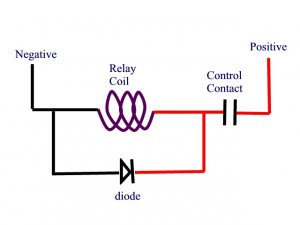
About the power supply. I'm an idiot when it comes to electrical. When you start talking about capacitors and amperage I zone out and think to myself, "oooo...look at the pretty lights!" A picture is worth a thousands words in my case my friend. I need to see how the finished project looks from the plug in the wall all the way to the device it powers or operates. Only then do I start to get "it".

Thank you so far. This has been a great source for something I want to include on my layout. If there is a way to do it, I'd love to give it a shot.

:D
 

Gary S.

Senior Member
Oct 13, 2005
1,576
0
36
Texas
My first question has to be: Are you on a shoestring budget here? Reason I ask, can we just spend the bucks on a ready made power supply, or do you want to actually build a power supply and try to save money?

Second question is: Do you want to wind your own magnets, or do you want something that can be put together pretty quickly?

And if anyone else wants to chime in here, you would be more than welcome!
 

tetters

Rail Spiking Fool!
Jan 21, 2005
879
0
16
50
Toronto, Ontario, Canada
Gary S. said:
My first question has to be: Are you on a shoestring budget here? Reason I ask, can we just spend the bucks on a ready made power supply, or do you want to actually build a power supply and try to save money?

Second question is: Do you want to wind your own magnets, or do you want something that can be put together pretty quickly?

And if anyone else wants to chime in here, you would be more than welcome!

Well. I wouldn't say money is no object. If I can do it for less and do it properly/better I will. However, if there really is no cost savings in the long run, then I'll stick to the tried and true methods. I like the idea of building stuff from the ground up. Call it bragging rights, as I take a great deal of pride in saying, "Yep, I made that myself".

I will also say that while I could never come up with this stuff on my own. I am good at following instructions (most of the time) and take my time to ensure I put things together right.

Thanks.
 

Torpedo

Member
Jan 20, 2007
278
0
16
79
You can increase the flux density by using square wire, which might be a wee bit hard to come by in 26AWG. :rolleyes: Another trick is to hammer the turns into each other as you wind the coil. The idea is to get rid of as much of the air space as possible. One inverter manufacturer actually used to do this on their production line.

Anybody care to experiment? :D
 

BigJim

Member
Nov 19, 2006
154
0
16
76
North Plains, Oregon
dixiemtn.com
Gary,

Is there a chance you could unwind one of the Kaydee coils and count the turns and measure the length? Knowing the resistance the length will give us the AWG. Knowing the turns will help design custom units that work.

...Jim
 

Gary S.

Senior Member
Oct 13, 2005
1,576
0
36
Texas
Err.... uh.... hmmmm.... that sounds like a lot of work.... Maybe this weekend? Maybe..... and then I have to wind it all back on there?

But for now, I can tell you this:

Wire Gauge = very small
Wire length = very long
Number of turns = a whole bunch

:)
 

Gary S.

Senior Member
Oct 13, 2005
1,576
0
36
Texas
I HATE it when I am composing a post that takes a long time because of interruptions, and then when I go to submit it, it is all lost because The Gauge has automatically logged me out. :curse: so here I go again starting over on the long post that just got wiped out. :curse:

Okay, if anyone is seriously contemplating using a system for uncoupling like mine, I can give some help. But let me put some figures on estimated cost.

My layout will be pretty big, about 75 linear feet of shelving, and will be a point to point industrial switching layout. I will need 10 electromagnet uncouplers (plus about a dozen permanent magnets)

10 Kadee #810 dual coil uncouplers = $120
Aluminum sheet for brackets = $7
Misc rod, screws, nuts = $12
2 conductor 20 awg cable = $10
sheet metal for extra sideplates = $2
24 volt DC power supply = $60
10 lighted pushbuttons = $50
10 N.O. contacts = $30
10 LEDs and resistors for pushbuttons = $5
10 24 volt DC dpdt relays = $40
10 bases for above = $30
8 feet Din Rail = $5
70 Din Rail Terminals = $20
1 24 volt Time Delay relay = $35
1 base for above = $3

wow. Over $400. Of course this would be less, perhaps way less, if you could scrounge this stuff or alternative items out of the scrap heap. Whatever you can scrounge will give direction to how you accomplish the tasks. For instance, I had a nice 24 volt supply already, which prompted me to do everything with 24 volts.

let me know what your thoughts are.
 

Gary S.

Senior Member
Oct 13, 2005
1,576
0
36
Texas
You guys are missing your chance!

Gauge Member #1: "Wow, Gary, that is a lot of money and time for an uncoupling system. I bought a wooden chopstick for 39 cents, it makes a great uncoupling pick, and I can uncouple anywhere and I never have trouble with unwanted uncouplings."

Gauge Member #2: "39 cents?! Dood, I went out in the yard and cut me a stick off a hickory tree and wittled it to a point and it works just grand, and it was F R E E.
 

tetters

Rail Spiking Fool!
Jan 21, 2005
879
0
16
50
Toronto, Ontario, Canada
Gary S. said:
You guys are missing your chance!

Gauge Member #1: "Wow, Gary, that is a lot of money and time for an uncoupling system. I bought a wooden chopstick for 39 cents, it makes a great uncoupling pick, and I can uncouple anywhere and I never have trouble with unwanted uncouplings."

Gauge Member #2: "39 cents?! Dood, I went out in the yard and cut me a stick off a hickory tree and wittled it to a point and it works just grand, and it was F R E E.

O.K. How 'bout I bought a hand held magentic uncoupler for 4 bucks at the hobby store, just 'cause I wanted to see how it works. It works well enough, but I still have to touch the cars to seperate them.
 

Gary S.

Senior Member
Oct 13, 2005
1,576
0
36
Texas
I had alot of the items I mentioned in my scrap heap, so my overall cost wasn't that much. Plus, I like electrical stuff, and had alot of fun building it, and am looking forward to getting it installed on the layout. I agree that the manual uncoupling is simple and inexpensive and "foolproof"... but for some reason I just have an aversion to it. So I didn't mind spending what I spent.
 

BigJim

Member
Nov 19, 2006
154
0
16
76
North Plains, Oregon
dixiemtn.com
Gary,

I would look at using less than 24 volts for the control side. Lots of great circuits using LM555 timers to drive relays. The coil voltage could be 12 volts with the switched voltage at 24.

I have done some experimenting with 4000 series CMOS devices. A moist finger on two screw heads does a great job of pulling down the input to ground with a 1 Meg Ohm pull-up resister. I am using NAND gates in a flip-flop circuit and a pair of LM555's to control tortoise switch machines but no reason the same input control wouldn't work to fire a LM555 in a one-shot arrangement to control a relay. The other great thing is you can parallel screw head pairs (or a solid rail to ground with screw heads along the side) to multiple locations at almost no cost. Since it is CMOS logic adding an "Only one at a time" feature shouldn't be too hard or expensive.

See http://home.cogeco.ca/~rpaisley4/LM555.html#2 for some great LM555 circuit ideas.

If your current is less than 2 amps there are a lot of cheap PC board relays available. See http://futurlec.com/RelDip.shtml at $0.80 each. Look around they also have 100 LED's for $5.00. If you use the LM555 to drive the relays they can be on the same project board and cut down on the number of DIN Rail terminals and off board wires.

I didn't see any diodes on your list. ANYTIME you are using relay coils you should have a snubber diode on the coil. Opening the connection to a coil can cause some very high voltages as the current wants to continue to flow at the same rate. An open circuit and 1.5 amps = a very very very high voltage. It will increase until it arcs somewhere. Probably the switch in your case but high voltage arcs are something we want to avoid anywhere near expensive DCC controllers.

...Jim
 

Gary S.

Senior Member
Oct 13, 2005
1,576
0
36
Texas
For awhile, I had toyed with the idea of using a "one-shot" delay with a 555 timer. I found an electronics forum, explained what I needed, and "presto", those brains had built me several circuits in mere hours. One of the circuits was for 24 volts but needed a LM312 voltage regulator to reduce things down to 12 volts for the electronics and a transistor to control the 24 volt relay that feeds the 1.5 amps to the electromagnet. The other circuit used a 12 volt supply and 12 volt relays. The 555 timer is robust enough to directly control a small 12 volt relay without a transistor, so this circuit was much simplified. These circuits were really nice.

However, since I already had a bunch of 24 volt relays, some lighted pushbuttons, DIN rail, terminal strips, time delay relay, and the power supply, it was just too easy and cheap to go all relay logic on this one. I've already got everything built and ready to install.

since the controls are all contacts with this, do I really need the kickback diodes? I know they need to be used where solid-state devices are controlling the coils. But generally, I don't see them used with mechanical-relay logic.

Your "touch" cirucit is really nice.
 

BigJim

Member
Nov 19, 2006
154
0
16
76
North Plains, Oregon
dixiemtn.com
Brain fart 2: Both the relays and the track coils should have snubber diodes.

Yes I would always use diodes. For the cost of 20 diodes (less than a buck) you will stop any arcing, switches will last longer, relay contacts will last longer and you won't induce radio frequency harmonics into surrounding wires that DCC might not like. Cost is less then 0.25% of project cost. I think this is called a no-brainer.

I would "cascade" your relays. Power to the first one. The NC connection from the first one goes to the power connection for the second. 2nd to 3rd, etc. The NO for each goes to the track coil. This way you never try and power two coils at the same time. Even though the last coil goes through 10 relays I am guessing you are using fairly heavy current rated relays. Even the PC board mount 2 Amp dip relays have a contact resistance of less than 50 milli ohm. Less than a 1/2 ohm total shouldn't have any negative effect.
 

Gary S.

Senior Member
Oct 13, 2005
1,576
0
36
Texas
I considered putting all the N.C. contacts in series to feed the pushbuttons. But I decided against it for the following reasons:

1. It would take more wires and be more complicated under the layout.
2. I figure that I will be the only operater the majority of the time, so I wouldn't push more than 1 button at a time anyway.
3. Because of the 4-5sec one shot, the odds of energizing 2 magnets simultaneously are fairly low (although a possibility with 2+ operators)
3. My power supply is good for 5 amps, so could handle 3 (possibly 4) without much concern.

About the diodes, I guess it would be cheap insurance to parallel them with the e-magnet coils and the relay coils. What particular diode do you recommend?
 

BigJim

Member
Nov 19, 2006
154
0
16
76
North Plains, Oregon
dixiemtn.com
It would be hard to find one that wouldn't work fine. The 1N4001>4007 series (50v>1000v) seem like a good low cost choice. On futurlec.com the 50v and 400v are both 10 for $0.20. Others a $0.05 each. You would need other stuff (Like 100 LEDs for $5.00 or their project boards, etc) to make the shipping worth it but @ $4 for up to $30.00, no mimimum and no credit card fee it is not to bad.

P.S. I know you have your power supply but others might be interested in 8 amp bridge rectifiers for $0.65. (3/4 x 3/4 x .275)
 

BigJim

Member
Nov 19, 2006
154
0
16
76
North Plains, Oregon
dixiemtn.com
ALso:

You don't want to parallel the diode. The voltage wants to increase when you open the switch. If you are using common ground the diode wants to be placed so that it conducts when the switched line of the coil is above the supply voltage.

Also was searching futurlec and found the L239 quad Push-pull amplifier for $2.90. This 36 volt 600 ma drive device could be used with a +- 12 volt supply to run four switch motors. With the push-pull and +- 12v supply one side of all of the motors could be ground so there would be 1/2 the wires from the control box to the switch machines. One wire and $0.75 per tortoise is not a bad deal.
 

Gary S.

Senior Member
Oct 13, 2005
1,576
0
36
Texas
Isn't this how the diode should be connected?

Also, that 8 amp rectifier might work for someone who wants to get a xfmr and build their own supply
 

Attachments

  • Picture1.jpg
    Picture1.jpg
    30 KB · Views: 79