stub switch or turnout

RailRon

Active Member
Nov 23, 2002
1,602
0
36
80
Trimbach, Switzerland
Tc, your solution to the problem is quite ingenious! :thumb: Is this only theory or are you really constructing such a turnout?

I had a similar solution with the control rod at the layout edge - almost the same arresting tin plate at the fascia board. Only I soldered a wire around the control rod instead of making a notch into it.

Ron

BTW: Did you draw this with 3rd PlanIt? Great pics and a very clear tutorial to follow!
 

TrainClown

Member
Apr 17, 2003
861
0
16
66
Saskatchewan, Canada
Visit site
Yep Ron, this is drawn with 3rd PlanIt. Now I got the swing of the software I can draw just about anything. I know some details are missing from the pix, but I just wanted to get the idea across.

No, I haven't built a turnout like this one. The turnouts I'm working on are more conventional with points and such. I have only built 2 of the planned 11 so I expect some of my new ideas will find their way onto my project. I'm building a switching yard, 15" x 6' as a test and practice. So far I'm having lots of fun. Made my own ties and spikes too. ;)

Your idea to wrap the rod with wire would work too, but I would want 2 rings of wire I think to help hold the tracks in place. If you had a brass tube the right size then you could cut thin slices of the tube to act as the wire wraps. Might be easier, but I like my "cuts in the brass tube" idea better I think. The tin plate would find the cut without having to fish for it.

Thanks for the comments.

TrainClown
 

Bill Stone

Member
Apr 20, 2001
528
0
16
90
San Dimas, California, USA
Visit site
Hey TC, some great ideas, excellent drawings and an excellent tutorial. One thing I particularly like is that your "control block" is guided like a drawer. Excellent.

Another advantage of the collar washers (that you may not realize) is that the rods can be free to rotate, which would relieve some strain on the joints (the control block is sliding in a straight line but the rails are moving in an arc.)

Many thanks.

BillS
 
:) :)
You all probably saw Chris' photo above, here it is again.

http://www.railimages.com/albums/chriswills/aaf.sized.jpg Thanx. Chris, hope you don't mind my link:)

That throwbar appears to me exactly like a piece of double
sided PC board painted black and turned edgewise in a slot
under the rails.:thumb:

It is soldered to four .010 brass 'L' angles which are soldered to
the bottom of the rails. The rails are held in gauge and the slight
flexibility of the circuit board helps it comply with the arc motion.
Only a narrow strip of the board is visible under the rails.:cool: :cool:

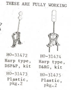
Harp Switch stand and remote actuation are details not yet
addressed.:sleeping:

Is dis a workable idea???
 

TrainClown

Member
Apr 17, 2003
861
0
16
66
Saskatchewan, Canada
Visit site
Yep Bill. I knew the rods could rotate. But I forgot to mention that, so, thanks for pointing that out. :thumb:

cidchase, sharp eye you got there. brass brackets soldered to a PC tie would do a good job of holding the rails in place, even on a conventional turnout...........I think. I don't know what a "Harp Switch Stand" looks like. Perhaps someone can find a pic and post it here :D


TrainClown
 

MasonJar

It's not rocket surgery
Oct 31, 2002
5,362
0
36
Ottawa, Canada
Visit site
Hi TC...

I was wondering if a 'Z' bend in the rod would provide a spring action to hold the points against the outside stops? Or are there outside stops on your plan - or do the notches/wire wrap hold the turnout in the correct place?

So many questions... This is a great thread! ;)

Andrew
 

Gary Pfeil

Active Member
May 7, 2001
2,510
0
36
Boonton NJ
Visit site
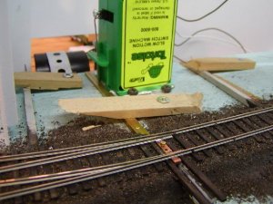
TC, Well thought out and nicely presented! Great job. I look forward to hearing how it works out. I won't be doing any track work till fall/winter. I plan to try brass wire and rod, hopefully it will work well. Seems simpler, but will certainly use the steel method if I need to. Didn't know it could be soldered actually. I'll be using Tortoise machines to throw. I had manual throws along the lines of what you show, my experience was that they get bumped into often. I suggest you mount them recessed in the fascia if possible. The photo shows a Tortoise mounted on top of roadbed on a pretty much standard (PCB tie) handlaid turnout. By using some variation of the scheme we've been discussing, I will eliminate the pcb tie, replacing it with an under roadbed bar which will take the Tortoise wire the same way as the photo. At least that's my goal. You'll probably do yours first, let us know how it works out!
 

Attachments

  • p1010451jpg.jpg
    p1010451jpg.jpg
    65.6 KB · Views: 82

60103

Pooh Bah
Mar 25, 2002
4,754
0
36
Brampton, Ontario, Canada
Visit site
3 ways

Note that the harp switch stands have 3 notches in them - one for each of 3 ways.
A thought: You could power a 3-way using 2 tortoise machines joined by a length of PCB tie, the Tortoises mounted facing each other. The center of the jpining piece would be attched to the throwbar. You would have to adjust the machines so that when they were in opposite position the turnout would be centered, and when they were both the same way it would be to one side or the other. (I don't think this is original)
 

Drew1125

Active Member
Jan 28, 2001
2,975
0
36
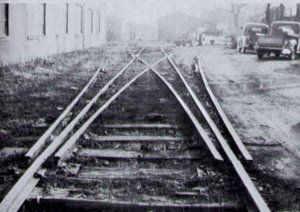
Here's another pic of a 3-way stub...this one was near Flemingsburg, KY
 

Attachments

  • stub1.jpg
    stub1.jpg
    27.8 KB · Views: 53