SPACE: 1999 MARK IX HAWK

bgt01

Exemplary Confidant
Jan 26, 2012
576
843
93
Ohio
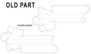
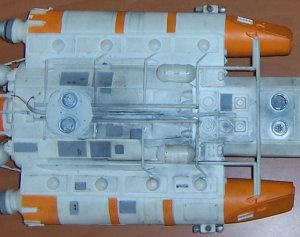
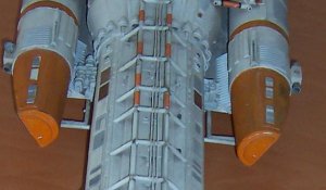
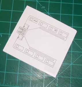
Every change or add on I’ve made has been based off the pictures I’ve found of the studio model. I’ve been lucky that there are some really good ones out there, but I’ve still had to contend with not being able to see some details clearly or not at all. That’s okay because I’m not trying for 100% accurate, just a lot more accurate. And, I don’t have the skills or hardware to replicate a lot of these details in paper. I think this model is a pretty good effort for an average builder. However, I’ve recently found a resource that shows I’ve gotten some stuff a good bit off. I joined the Eagle Transporter forum a while ago. It never occurred to me to check there when I started. I recently found a thread where a member is making a studio scale model using the original kit parts. His pics show a lot of the details I had to guess at, and mostly I guessed wrong:(. I never thought to research just the kit parts for details or for fit and finish. It would have been a big help. So, if anyone out there tries a redo like mine you might want to research the plastic kits, if possible, for reference. Oh well, at least I’m not TOO far off. ;)
 
  • Like
Reactions: vipers7

bgt01

Exemplary Confidant
Jan 26, 2012
576
843
93
Ohio
SOLAR PANELS

The old solar panel part is just a flat piece of paper with no sides. I made mine from scratch starting with redrawing the top panels and gluing the new parts to 1mm chipboard. I printed out extra panels, glued them to the same 1mm chipboard, cut out the black rectangles and edge colored the sides with silver Sharpie to more closely match the studio model. These were glued back on the top panel.
 

Attachments

  • SOLAR PANELS_1.jpg
    SOLAR PANELS_1.jpg
    210.4 KB · Views: 20
  • SOLAR PANELS_2.jpg
    SOLAR PANELS_2.jpg
    88 KB · Views: 16
  • SOLAR PANELS_3.jpg
    SOLAR PANELS_3.jpg
    44.1 KB · Views: 16
  • j_1.JPG
    j_1.JPG
    397.3 KB · Views: 17
  • j_2.JPG
    j_2.JPG
    448.9 KB · Views: 16
  • j_3.JPG
    j_3.JPG
    185.7 KB · Views: 16

bgt01

Exemplary Confidant
Jan 26, 2012
576
843
93
Ohio
Next I made the 4 short ends. They all have 5 recessed holes. Again, I used my metal pick to punch out the holes in the top part. I used my X-acto to shave off the raised areas on the backs so the new recessed backs would sit flush. These got glued to the new backs and trimmed to fit.

The long sides are just strips of card stock cut to fit. Except for the port side left panel. It is supposed to have 6 recessed slots. I trimmed these out and glued a new piece of colored card from behind. I colored the card with silver Sharpie to provide a little contrast.

To make the parts a little sturdier and give the bottom something to attach to, I cut squares of chipboard and glued them into stacks of 3 and attached them to the bottom of the top panels. You can’t really see the bottoms once they are on the model, so I saved a little effort and made them out of 1mm chipboard colored with silver Sharpie. The gluing sequence was: 3 sides, then squares, then bottom, then the final side.
 

Attachments

  • j_4.JPG
    j_4.JPG
    225.5 KB · Views: 12
  • j_5.JPG
    j_5.JPG
    163.2 KB · Views: 11
  • j_6.JPG
    j_6.JPG
    115.8 KB · Views: 10
  • j_7.JPG
    j_7.JPG
    115.9 KB · Views: 10
  • j_8.JPG
    j_8.JPG
    350.9 KB · Views: 10
  • j_6.JPG
    j_6.JPG
    115.8 KB · Views: 9

bgt01

Exemplary Confidant
Jan 26, 2012
576
843
93
Ohio
At assembly, I couldn’t find any pics that clearly showed all the way around the pieces that connect the panels to the hull (1 piece or 2?, short end structure?), so I had to make my own call on some of this construction. I settled on 1 base for each panel. The piece glued to the bottom of the panel is 67 lb. white cover. The fins are made from the same white cover. I measured out the 3 fins on the long axis and cut the slants in by 2mm. I cut little squares to fill the gaps between the fins. I cut the remainder of the fins at 2mm and glued them around the outside using Super Glue gel for a quick seal. Finally, I glued on the bottom, which is slightly smaller than the top and also made from 67 lb. white cover. The last step was to add the 2 white pieces that connect the panels at the top.

Sadly, once I finished this I found the pics of the replica Hawk parts that clearly show I’ve made the bottom almost completely wrong:mad:. It is supposed to look like the reference pic attached. Along with having the wrong detail, my 2 piece version is too wide and sticks off the sides of the hull. I’m either going to have to rebuild the whole thing or cut off the base and rebuild just that.
 

Attachments

  • j_9.JPG
    j_9.JPG
    253.6 KB · Views: 11
  • j_10.JPG
    j_10.JPG
    252.3 KB · Views: 12
  • j_11.JPG
    j_11.JPG
    152.1 KB · Views: 14
  • SOLAR PANELS_4.jpg
    SOLAR PANELS_4.jpg
    64.1 KB · Views: 11

bgt01

Exemplary Confidant
Jan 26, 2012
576
843
93
Ohio
ADDING DETAILS 1

I’m going to do additional greebling as I go because that will be easier for certain areas. I added the panel that connects the top of the command module to the top of the fuselage. The two circle areas on the studio model look like small take-up reels (for those of you old enough to get that reference:D) so that’s what I went for. These parts are card stock glued to 67 lb. white cover.

Next, I added some of the small rectangles that go around the side seam of the command module/fuselage (there are none on the bottom seam). My guess is their purpose on the studio model is to hide the seam. I cut several 3mm x 2mm rectangles. That size was a guess which proved to be a little big, so I trimmed a little more off the length. Since the paper model’s dimensions are different and it has straight edges instead of all curves, I couldn’t fit match the amount or exact placement of rectangles. Again, I went for getting it close.
 

Attachments

  • k1.JPG
    k1.JPG
    98.4 KB · Views: 14
  • k2.JPG
    k2.JPG
    217.3 KB · Views: 15
  • k3.JPG
    k3.JPG
    135.4 KB · Views: 13
  • k4.JPG
    k4.JPG
    308.3 KB · Views: 15
  • k4.JPG
    k4.JPG
    308.3 KB · Views: 14
  • k5.JPG
    k5.JPG
    185.6 KB · Views: 14

bgt01

Exemplary Confidant
Jan 26, 2012
576
843
93
Ohio
WING ASSEMBLY

Time to assemble the wings! First, the wing guns are attached. I used regular glue to give myself some positioning leeway. Once set, I used a little Super Glue gel to lock everything in position. The way I made the wings let the guns sit nicely and look a lot closer to the studio model. The only problem is the port side wing got tweaked and looks a little off. I didn’t want to go back and make another so I worked it out the best I could.

Next up, I fabricated the pieces that connect the targeting sensors to the wings. Again, trying to get them close to studio pics but I don’t have good pics from all sides. The bases are glued to 67 lb. white cover and trimmed. The connectors are 2 layers of the same cover. Finally, both sensors are glued in to place.
 

Attachments

  • l1.JPG
    l1.JPG
    155.7 KB · Views: 9
  • l2.JPG
    l2.JPG
    168.9 KB · Views: 9
  • l3.JPG
    l3.JPG
    156.4 KB · Views: 9
  • l4.JPG
    l4.JPG
    350 KB · Views: 9

bgt01

Exemplary Confidant
Jan 26, 2012
576
843
93
Ohio
I added the small white trapezoid on each wing by cutting a piece of 67 lb. white cover to size and gluing them on with Super Glue gel.

When I test fit the wings, it was clear the port wing was going to have a really bad slant. The main “box” shape had gotten cantered forward, so if the wing was glued on level the wing gun was going to be pointing up:mad:. I performed some corrective surgery by cutting the end flap off the wing where it connects to the fuselage. This let me adjust the wing shape to where I could get the wing and gun to be much more level with the ground;). Once that was done, both wings were glued on with regular Elmer’s Paper Gel. I used the table top to keep the wings level while positioning and drying. When the glue firmed up I locked the wings in place with a little Super Glue gel around the seam.

One change I’d make to this procedure is I’d put the targeting sensors on last. Due to the adjustments I had to make to the wings the sensors aren’t quite as level as they could be, but they aren’t so bad I wanted to start over.
 

Attachments

  • l5.JPG
    l5.JPG
    94.5 KB · Views: 26
  • l6.JPG
    l6.JPG
    144 KB · Views: 27
  • l7.JPG
    l7.JPG
    356.9 KB · Views: 31
  • l8.JPG
    l8.JPG
    304.2 KB · Views: 29
  • WING FINAL_1.png
    WING FINAL_1.png
    301.9 KB · Views: 29

bgt01

Exemplary Confidant
Jan 26, 2012
576
843
93
Ohio
BOOSTER PYLONS

On the JayBats model, the booster engines are connected to the fuselage by two pylons. On the studio model, the boosters rest on a flat panel that connects to the bottom of the rear main fuselage. This area has a lot of greeblies (lines, tanks, framework, boosters) that are a huge part of the Hawk’s identity. In “real” world terms, it’s kind of a design mess and shows the rush the model makers were in, particularly since they forgot to add any landing gear! It’s really just a lot of mattress buttons, washer heads, wire and plastic model sprue.

This is the first part for the model that’s 100% scratch built. I started by making some paper templates and adjusting them until they fit correctly around the fuselage. Then I drew up the part in InDesign using my model pics for reference. As before, I had to go for a balance between looks since the paper model dimensions are different than the studio model. The forward center details are pretty small at this scale and would become a challenge later on.

With the design finalized I printed the part onto label paper. I used double-sided tape to layer 2 pieces of 67 lb. white cover, which kept the cover from curling and gave me a solid, thick panel. Then, I applied the label and trimmed out the part. I printed out additional panels onto regular card stock to supply the raised details. Almost all the raised parts were also glued to 67 lb. white cover. The small domes are Glamour Glitz ivory accents I got at Hobby Lobby. I already had them before I started this model and luckily they were a perfect fit.:D
 

Attachments

  • BOOSTER PYLONS_1.jpg
    BOOSTER PYLONS_1.jpg
    50.5 KB · Views: 18
  • BOOSTER PYLONS_2.jpg
    BOOSTER PYLONS_2.jpg
    280 KB · Views: 14
  • BOOSTER PYLONS_3.jpg
    BOOSTER PYLONS_3.jpg
    100.4 KB · Views: 18
  • m1.JPG
    m1.JPG
    209.6 KB · Views: 16
  • m2.JPG
    m2.JPG
    176 KB · Views: 15
  • m3.JPG
    m3.JPG
    436.4 KB · Views: 14

bgt01

Exemplary Confidant
Jan 26, 2012
576
843
93
Ohio
The detailed area at the front center took a lot of work. It has a lot of little bits that took a lot of time to draw out. The smallest details (the 4 little rectangles and dual circles on the outside flaps, the small boosters in the center) were almost two small to cut out. As is they aren’t the greatest when you get up close. And because there are so many little parts glued on these areas are very fragile. I had to re-glue a few pieces that came off during handling. This was a huge exercise in patience.
 

Attachments

  • m4.JPG
    m4.JPG
    127.5 KB · Views: 7
  • m5.JPG
    m5.JPG
    486.6 KB · Views: 7

bgt01

Exemplary Confidant
Jan 26, 2012
576
843
93
Ohio
I dry fit the panel several times before gluing. On the final fit, I got it in place and used a sharpened toothpick to spread Super Glue gel along the inside front center seam. The Super Glue gel is perfect for this work and gives a solid seam. Using the center as an anchor, I slowly worked my way around to the rear gluing the panels to the fuselage, keeping them as level as possible with the main body. Overall, it’s pretty good. The model isn’t 100% level across all the parts, but that’s the nature of the paper beast.;)
 

Attachments

  • m6.JPG
    m6.JPG
    343.7 KB · Views: 8
  • m7.JPG
    m7.JPG
    484 KB · Views: 7
  • m8.JPG
    m8.JPG
    379 KB · Views: 8

bgt01

Exemplary Confidant
Jan 26, 2012
576
843
93
Ohio
With the panel in place, I added all the little triangle-like greeblies around the forward seam. These are dome-like structures on the studio model, kind of like the end of a pen. I couldn’t replicate that, so I went with a somewhat similar flat version. I had to do some creative trimming to the ones that meet with the angled area. Again, since the paper and studio dimensions differ I don’t have the same amount of triangles on my model. Also, in the initial stage of redesign I failed to design in the band that goes around the seam of the main and rear fuselage where these triangles go. It’s a fairly big omission and I’m not sure how I missed it, but I was way too far along in the construction process before I noticed it, so I decided it wasn’t a deal breaker.
 

Attachments

  • m9.JPG
    m9.JPG
    592 KB · Views: 11
  • m10.JPG
    m10.JPG
    106.1 KB · Views: 11

bgt01

Exemplary Confidant
Jan 26, 2012
576
843
93
Ohio
Next up, I attached the boosters to the panel. I thought about holding off until I designed the details that go on the panel between the boosters and the fuselage but decided against it. I wanted to get the orientation of the boosters correct because that’s the most visible way to screw up. With the boosters in, I can add the rest of the detail using tweezers and setting it with regular gel glue, which will give the plenty of time to get the parts in position. I ran a bead of Super Glue gel down each panel edge, lined that up with the seam of each booster and held it in place until it set. Now the boosters are on securely, but still have a little give for when I add the details and the support framework.

Now she’s starting to really look like a Hawk!:D
 

Attachments

  • m11.JPG
    m11.JPG
    444.5 KB · Views: 29
  • m12.JPG
    m12.JPG
    526.6 KB · Views: 27

Revell-Fan

Co-Administrator
Staff member
Administrator
Moderator
Aug 1, 2009
11,595
12,338
228
Vreden
Remarkable progress! What do you think, would it be possible to add the missing band later, or at least cheat so that it looks as if it were there?
 

bgt01

Exemplary Confidant
Jan 26, 2012
576
843
93
Ohio
Thanks @Revell-Fan . No, it can't be added later on this model. On the actual studio model, there is a gap between the rear fuselage and the main (narrow) fuselage. The band covers that up and it's fairly wide. You can see in the reference pics how it butts up against the upper rectangle details on the hull. To add it now, I'd have to cut off the entire rear section along with my new panel and rebuild the entire thing. That's just too much work down the drain for that. It's now a detail that jumps out and hits you in the face that it's missing so, I'll just have to live without it. Not the end of the world, but sad.:(
 

Attachments

  • band1.jpg
    band1.jpg
    95.6 KB · Views: 18
  • band2.jpg
    band2.jpg
    54.1 KB · Views: 18

Rhaven Blaack

!!!THE MAN BEHIND THE CURTAIN!!!
Staff member
Administrator
Moderator
Jun 12, 2009
12,493
9,857
228
Oregon
www.deviantart.com
Another thing that you might be able to do. Would be to scrape off the little triangles and then put the band in place and then put new triangles in place.
The thing is, you will have to tightly push the ends of the band into the crack between the flat panel and the fuselage. If you are very careful, you can do it and still have it look good.
 

Rhaven Blaack

!!!THE MAN BEHIND THE CURTAIN!!!
Staff member
Administrator
Moderator
Jun 12, 2009
12,493
9,857
228
Oregon
www.deviantart.com
As for the triangles, you can easily take a thick toothpick or bamboo skewer (that is sharpened to a point) and use that to shape the triangles into the little half cones.