Pictured is part of the 3 track main module I am building for GATS in December. I would like to place a signal bridge in such a way as to show at a glance in either direction, whether a route is open, especially with that double slip switch. I know that LEDs are polarity sensitive and am hoping that that can factor into a cure the is easy on the budget. Any help would be greatly appreciated and would be acknowledged when entered into the NMRA Regionals in May '04.
Signaling setup...
- Thread starter shaygetz
- Start date
You are using an out of date browser. It may not display this or other websites correctly.
You should upgrade or use an alternative browser.
You should upgrade or use an alternative browser.
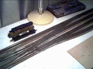
To help, the turnouts are Peco power routing type with the exception of the Shinohara double slip switch. I'm not looking for a true-to-prototype signal set-up, just something to let the operators know that the route ahead is clear.
Have you thought of mounting switch machine controls on track diagram in fascia at this place. Incorporating lights to indicate direction of switch path (or as interlocked routes in series using rotary wafer switch(es))this is easiest way to go to impart information to operator<that I assume has some kind of hand held DBC,RC,DCC,CC,or IR walkaround throttle>.
This is because model railroad LED signals require you to get up close and personal to read them unless the lightlevel is low. Semaphores mighy resolve this, but require either more skill to build, or more dough to purchase. You have some kind of price constraint ? Besides, there are only expensive operating semaphores that can be used on a signal bridge (also has to be 'HO' scale or larger, I ken).
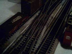
By the way I do not see any double slip switch in that picture , but that could be because of low light level and my eyes. Also it would be helpful for you to define "CHEAP". Does time have no value? Are you going to take raw material , that is brass bar, tube and sheet metal to fabricate your signal bridge(s), and signals?.
You would need two bridges at least , I ken. That is because you want the operators to know their instructions prior to being at the turnouts. Are you using electric or pneumatic switch machines, or choke cables and Eschelmann Links et al ? So what are you using to throw turnouts and what is "Cheap" are in need of answering, in order to reach opening day , with respect to your matter.
Good-Luck, PJB
This is because model railroad LED signals require you to get up close and personal to read them unless the lightlevel is low. Semaphores mighy resolve this, but require either more skill to build, or more dough to purchase. You have some kind of price constraint ? Besides, there are only expensive operating semaphores that can be used on a signal bridge (also has to be 'HO' scale or larger, I ken).
By the way I do not see any double slip switch in that picture , but that could be because of low light level and my eyes. Also it would be helpful for you to define "CHEAP". Does time have no value? Are you going to take raw material , that is brass bar, tube and sheet metal to fabricate your signal bridge(s), and signals?.
You would need two bridges at least , I ken. That is because you want the operators to know their instructions prior to being at the turnouts. Are you using electric or pneumatic switch machines, or choke cables and Eschelmann Links et al ? So what are you using to throw turnouts and what is "Cheap" are in need of answering, in order to reach opening day , with respect to your matter.
Good-Luck, PJB
Originally posted by pjb
By the way I do not see any double slip switch in that picture , but that could be because of low light level and my eyes. Also it would be helpful for you to define "CHEAP". Does time have no value? Are you going to take raw material , that is brass bar, tube and sheet metal to fabricate your signal bridge(s), and signals?.
Good-Luck, PJB
I apologize for taking so long to follow up on your post. By "easy on the budget" I wasn't looking for cheap, just economical. There is an electronic circuit out there that does just what I'm looking for for $179.95.
Three factors govern this particular setup, one being the audience. For the most part, the average attendee could care less for prototypical accuracy, they just want to see the trains running. Second is operation, because it is part of a show layout, operators simply want to know if the route is clear. Trains travel 'round and 'round and are swapped out for new ones as members assemble and send them out. This module leads directly into the yard throat, To what part of the yard they will be heading is based on the final setting of no less than four sets of switch points. Third and final, it is my home layout, based on a simple but effective hairpuller designed by the late John Allen. My only change was the addition of my favorite piece of trackage, the double-slip switch, found in the center of the plan.
Attachments
The swithches will remain manual, the Pecos are well designed and lock into position. The Shinohara does not so some kind of mechanism, perhaps a DPDT slide switch mounted under the layout, must be provided. Maybe using the poles of the DPDT switches to route power to dwarf signals mounted near each switch point would be one idea. I do appreciate your input into this, thank you very much.
Originally posted by pjb
Have you thought of mounting switch machine controls on track diagram in fascia at this place. Incorporating lights to indicate direction of switch path (or as interlocked routes in series using rotary wafer switch(es))this is easiest way to go to impart information to operator<that I assume has some kind of hand held DBC,RC,DCC,CC,or IR walkaround throttle>.
Since this will be operated from both sides, from the back as a module and from the front as a home layout, I would have to do both sides. Not a daunting prospect, as long as I mounted all of it recessed into the sides to protect it during transport and design a way to "lockout" the side that faces the audience. We use Digitrax DCC so there are no other special wiring considerations.
The easiest way that I see to do it is to set up block detector units on each of the lines. Then use them to switch your LEDs. They make dual color LEDs, Red if the polarity is one way, and green if it is the other way. A few el cheapo DPDT relays and you're in business. If you need them, I can whip up some simple schmatics and part #s and sources. Hope this helps.
Originally posted by Pitchwife
If you need them, I can whip up some simple schmatics and part #s and sources. Hope this helps.
That would be great and much appreciated. I can follow schematics just fine, I spent too much grey matter in the 70s to design my own. If you make Radio Shack the primary parts source, I'll be in Nirvana.
Give me a couple of days to put the circuit in a form I can send you or post. Also I'll turn you on to some much better places than RS. Much more selection, better quality and cheaper to boot.
It would help me if I knew what kind of block detectors you plan on using. The only ones I'm realy familiar with are infared. I know that there are a lot more ways to do it. If you know of any or know someone that does (like you couldn't find any here on The Gauge ) it will help me out. Otherwise we'll just do what we can.
It would help me if I knew what kind of block detectors you plan on using. The only ones I'm realy familiar with are infared. I know that there are a lot more ways to do it. If you know of any or know someone that does (like you couldn't find any here on The Gauge
) it will help me out. Otherwise we'll just do what we can. Since it is part of a modular layout, there really wouldn't be any need for a block detector, just something that would run off of the point routes as they are switched. As for RS, I only thought of them for convenience and time's sake, the GATS show is just two months away (I swore I'd never get in a deadline for a hobby )
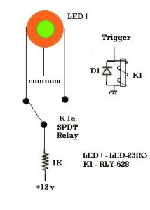
)OK, this is your basic diagram. The LED has three legs, one of which is the common cathode. The part number I gave is for an 8mm high intensity light that could be seen from a distance. The relay is your basic 12v DPDT and the other parts are a common diode and resister.
I got the part numbers from All Electronics www.allelectronics.com . I've bought from them before and have had good luck with them. Prices are good too. The LEDs run 2 for $1.00 (smaller ones are a little cheaper but I figured you wanted showy rather than proto, and the relays are $1..25.
All you need to do is supply +12v to the trigger and depending on how you want the LED set up it will switch from one color to the other.
You can use your point routes to determin if a relay gets a signal or not.
Hope this helps.