Problem with ballasting - need advice

SmolderZ

Member
Sep 27, 2003
93
0
16
40
The Netherlands
Hello people,

I've just layed the main line on my module and it might be smart for me to ask this first before I continue with balasting it completely.

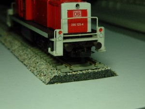
I use a small strip of cork, it's 12mm wide and 1,5 mm thick which fits exactly under the rail. (it's Z-scale) When adding ballast I didn't like the small edge it created. That's why I want to eliminate this small edge by adding an extra material so it drops off more smooth and realistic.
What kind of material can I use for the yellow part in this picture?

raildilemma.JPG


Thanks for the help!
 
N

NWP-fan

I've seen people use caulk for that purpose in larger scales - just lay down a strip of caulk at the edge of the cork and then run your finger along it to smooth it out, let it dry, then ballast.

If that's too big for practical use in Z-scale, I've also seen similar things done using diluted plaster, applied with a cake-decorating nozzle.

Anyone else?

Happy railroading!
 
N

NWP-fan

jon-monon said:
If caulk, you might try the paintable stuff, slippery slimey silly-cone might not take kindly to glue, since it hates paint. Perhaps a wood filler would be more accepting.
Yes... I was thinking of the white chalky stuff used in bathrooms, which dries into something much like plaster. Wait, that's called grout, isn't it? *whacks self on head*
 

Pitchwife

Dreamer
Apr 23, 2001
1,728
0
36
71
The middle of nowhere Oregon
Visit site
I had the same problem with an N scale module I am working on. My solution was a roll of cork that I got from the local hardware store. I don't recall the thickness, but it was thinner than the cork roadbed I started with. It came in a 4'X8' roll and cost about $14US. I layed it over the foam that I am using for a base, layed the track over it using pins to hold it in place. Once I get the track the way I want it I will outline the roadbed, leaving as much of an edge as I think looks good, and then will cut the cork and trim it as needed. Really makes curve and turnout roadbeds easy to make.
 

RailRon

Active Member
Nov 23, 2002
1,602
0
36
80
Trimbach, Switzerland
I'm adding a third vote for shaping the ballast slope with additional ballast.

A height of only 1.5 mm (even 2.5 mm when you add the tie thickness) won't use up that much ballasting material. Besides there is one step less of work to do.

Ron
 

jcami

New Member
Sep 25, 2004
12
0
1
74
Malta - Ta' Xbiex.
Roadbed

I use a dark grayish carpet underlay material some 4mm thick which I buy in widths of one and a half meters at a cost of $5 per sq. meter.

I cut it in 2 inch strips and pass it through my driller mounted at 45 degrees with a circular saw cutter. This gives me the chamfer I need on each side of the roadbed

I then paint the surface with adhesive tackifier and then sprinkle with ballast material. (I use sand from the beaches or sand blasting material - both of which take ages to wash and dry!) - but bith are really cheap to obtain! I use newspapers to compress the ballast onto the adhesive to ensure good contact and leave to dry. When dry, I dust off the excess and give a once over with the adhesive. This ensures that there is no loose ballast to interfere with the rolling stock.

I then lay the underlay on the layout and pin the track to it as required. I cut thin wedges off to allow the material to go round the curves.

Personally, I am happy with this result, although it is not 100% realistic. To be more realistic I would have to sprinkle some more ballast over the track to fill in between the sleepers, then spray with 'Scenic Cement' - made by Woodland Scenics.


Joe.
 

jcami

New Member
Sep 25, 2004
12
0
1
74
Malta - Ta' Xbiex.
Hi all,

I am still new to this site and am still learning how to use it. I have attached a picture to show the result of my previous reply on road beds and ballasting. I hope you like!

Joe.
 

Attachments

  • DSCF0458.JPG
    DSCF0458.JPG
    36.6 KB · Views: 278

RailRon

Active Member
Nov 23, 2002
1,602
0
36
80
Trimbach, Switzerland
Hi Joe,

welcome to the Gauge. Nice to have someone here from Malta! (I've been on your islands in my holidays - Comino, to be exact - but I must confess I've never seen (and looked for) something railroady on these beautiful islands! :eek:ops: :eek:ops: :eek:ops: )
I then paint the surface with adhesive tackifier ...
What do you use as a 'tackifier'. Is it a liquid or a spray or... ? And: Is it messy to use?

I'm asking because the result looks really fine! :thumb:

Ron
 

jcami

New Member
Sep 25, 2004
12
0
1
74
Malta - Ta' Xbiex.
Hi Ron,

Nice to hear from someone in Switzerland. I was there in 1999 and in 2000. Beautiful Country! I travelled from station to station taking photos since my layout is supposed to simulate this country. I already have some 20 Swiss locomotives in HO which are all Roco with the exception of two Bemo in HOm.

The tackifier I use is a thick water based glue and is quite messy if not handled properly. It is exceedingly 'sticky'. When dry, however, it could be persuaded to be removed from your fingers and from the brush with the aid of luke-warm water and possibly some solvent. Having said that, I took precautions: First of all I used the glass table in the back garden, covered it with newspapers, laid some 5 strips of this roadbed and taped them together so that the grove made between one strip and the other would get an abbundant coating. Last, but not least, I got Chris, my friend, to do the job!!!!! :p

I do not know what this tackifier's trade name is but as soon as I find out I will let you know! You see, the shop assistant gave me some half a liter from a larger container as a sample!

I am attaching another photo, this time using sand from the beach!


Joe.
 

Attachments

  • DSCF0461.JPG
    DSCF0461.JPG
    40.9 KB · Views: 258

RailRon

Active Member
Nov 23, 2002
1,602
0
36
80
Trimbach, Switzerland
Joe, this is a beautiful model of the Be 4/6. Here's the original - just for comparison.

As a suggestion: When you have finished the ballasting of the track (yours look really good), give it a wash of a dark rusty red (e.g. black and siena brown india ink, thinned with water or alcohol --> inkahol :D)

If you should have questions about Swiss railroads, just ask! (Of course this is an offer to ALL of you Gaugers :))

Ron
 

Attachments

  • Be 4-6.jpg
    Be 4-6.jpg
    46.9 KB · Views: 248

jcami

New Member
Sep 25, 2004
12
0
1
74
Malta - Ta' Xbiex.
Diode Matrix for operating Tirnout motors.


Hi Ron,

I have browsed on your website and noticed that you too have a diode matrix/Capacitor discharge unit to operate your turnouts. Also I have noticed that you too have an underboard "shadow station".

I too would like to show you my layout, but since I do not have a website, I will try to post the following write up with pictures.

I hope you like.


Joe.


Introduction
First of all, I would like to clarify that my interest in Model Railways includes all makes, including Marklin 3-rail AC - 'Digital' included. My preference however lies with 2-rail DC and my preferred make is Roco. My choice has been qualified by a sequence of events starting in 1958 when I was only 8 years old. My father had bought me a few trains over the years and it was later not considered feasible to change from the DC system.

Space.
I know that one of the options available to most Model Railway enthusiasts is to build a 0.5-meter shelf on 3 walls of the hobby room. (Widening to 1 meter at opposing ends) This provides the basis for a good layout with easy reach of all areas and the option of a nice backdrop. This type of layout is very good in terms of space because it leaves you with a lot of space in the center of the room and at the same time allows long runs for the trains. (Modular Layouts are not popular in Malta because there is no culture of participating in meetings that make such layouts so appropriate)

In my case however, the awkward shape of my garage with rounded walls and oddly placed apertures has led me to design my layout in a very different way. First of all I am limited to a maximum layout area of 5m x 1.25m and since this was not enough for what I had in mind, I decided to have 2 levels.

Configuration.
The upper level was to have a Station, a Marshalling Yard, a Locomotive Depot with Turntable and Round Houses and also a Hill leading to a Bridge. In addition, this level was to include the Faller Car System and a little Mountain Village.

image002.jpg


The lower level was to have a large shadow station - the largest that would fit!

image004.jpg


Structure.
A large 6 wheeled trolley, made of welded metal hollow section and painted with 'Hammerite' was constructed. Thus, the layout could be moved to the middle of the room when required. As can be seen from the picture below, the trolley has a welded support arm with wheels, on which, the top layout could slide forwards and backwards to expose the bottom layout when necessary. The two layouts were made of boards made of 13 mm plywood. Each board is mounted on aluminum beams lengthwise (for stability) with shorter 'rails' at right angles upon which the boards could run over the wheels on the welded metal arms.

This trolley has 4 very large and deep drawers where I keep my empty rolling stock boxes. The full ones I keep in a separate place. This helps to keep the weight off the trolley and also provides for easy location of the empty ones. These drawers are deep because I like to keep the boxes upright with the identifying number on each box visible!

As far as I know, the sliding feature described above is the only one of its kind in Malta and in practice, it works well. When the layouts are locked in position, flexible track is used to join the lower layout to the spiral, which 'hangs' from the top layout. As can be seen from the photos the spiral is slightly larger than the baseboard. I hope that the following pictures help to demonstrate this design.

image006.jpg

THE SLIDING FEATURE

image008.jpg

FRONTAL VIEW OF THE UPPER AND LOWER LEVELS
(Note the deep drawers used for storing boxes upright)

image010.jpg

FRONTAL VIEW BETWEEN LEVELS (Also showing Route Control Panels)

image012.jpg

THE SPIRAL CONNECTED TO THE LOWER LAYOUT BY FLEXIBLE TRACK.

(The string is to prevent those coaches moving up the spiral from crashing to the floor if they got uncoupled and came back at full speed - a common occurrence before the spiral was correctly set)

Power.
So far, I have dealt with aspects that might interest all enthusiasts including Marklin enthusiasts. If I may now, I would like you to permit me to dwell for a very short time on my DC control panel which I have very much at heart. Although this might appear to be something complicated, it is not. In its basic form, each controller is made out of 5 components and therefore the tendency to produce more than what is required is of great temptation.
In my case, my panel has 10 Controllers:

Controller 1. For Main Line
Controller 2. For Hill & Bridge
Controller 3. For Marshalling Yard
Controller 4. For Turntable Area.
Controller 5. Extra (Intended for later use on a Mountain Rack Railway.)

The other 5 controllers to be used as for the above but for Catenary use.

The simple design of this electronic controller has been discovered by Roger Amos and described in his book called 'Complete Book of Model Railway Electronics'.

The simple circuit (only 5 components) is for DC Analogue Locomotives only. The current gain theoretically approaches 1,000,000 and consequently speed regulation is excellent. It produces better stop/starts than most PWM Controllers. Motors are extremely silent and always keep cool. The feedback system allows for constant speed along uphill / downhill gradients. Each controller can theoretically handle 10 amps - although in practice one would not need more than say 1.0 or 1.5 amps at the most. I have chosen to keep my control panel in a drawer to keep it out of the way when not in use. If anybody needs more info about this, please send me an e-mail. I also have a printed circuit board, which I could make available to any body interested.

image016.jpg

CONTROL PANEL FOR DC ANALOGUE. (Slides under the base-board, out of the way, when not in use)

Digital
When Digital became more popular and models with sound became available, I was very much tempted to consider this option seriously. The prospect of having to install some 60 decoders to my present collection of locomotives, however, was considered an unnecessary expense especially since I am quite certain that in future sound decoders will become available for retrofitting. Not withstanding the above, I did install a digital system, which I use only to show off my S. 3/6 with sound. Traction on my 5% helix is disappointing.

image017.jpg


My Main Line is fitted with two switches. The first switch is used to select between Digital and Analogue. The second to choose etween Pulse Width Modulated Analogue or the Panel explained above - which I prefer hands down.

Route Control
I was once discussing this subject with a dear friend of mine, who has since passed away. He had explained to me the principles of using a diode matrix for Route Control. This filled me with excitement and some months later, I wanted to use this idea on the lower layout. This consisted of a panel with 'push-to-make switches', which activated a pre-determined series of turnout motors to their straight or curved positions as required. This was done via a 'Capacitor Discharge Unit'. The CDU is a very efficient way of activating point motors because it releases a surge of power, which is sufficient to power a number of motors. The CDU used (made by Guagemaster) has enough power to activate in excess of 21 Roco Turnout motors simultaneously.

Turnout motors are a bit heavy on current. It is not unusual that a point motor uses 0.8 amps to work well and therefore to avoid using heavy cables, a CDU is recommended. A CDU works only on DC.

I later wired in reed switches and relays to the live sidings of the lower layout and fixed magnets to the locomotives. By so doing, I created the ambient for automation. The ensuing result is that I could select any one of the trains in the 10 live sidings below; call any one up to the Station in the upper layout and subsequently, when the train returns to its original siding below, it isolates itself in and releases the next train, which automatically leaves its siding to complete the same sequence. In this way I get variety, in the sense that I see ten different trains coming up to the station above before seeing the first one again. - a bit closer to reality?

When it came Route Control for the upper layout, I decided to do something different since I did not need the facility of automation as described above. I decided to wire in the original point switches in addition to the 'Press-to-make' switches. These Roco switches enable me to override the Route Control system if I so require, and at the same time provide visual return indication, since these are equipped with bi-colored light emitting diodes.

I know that it is not possible for me to give too much detail of the wiring here, as there is the risk that some of you might get bored. I would however be delighted to answer any questions to those of you who are considering a cheaper alternative to using Digital for Route Control!

image019.jpg

ROUTE CONTROL PANELS FOR THE UPPER & LOWER LAYOUTS
(The white switches are for the uncouplers)

image021.jpg

THE MARSHALLING YARD WITH THE LOCOMOTIVE DEPOT IN THE BACKGROUND
(Photo taken some time ago)

image022.jpg

THE MARSHALLING YARD
With the elevated roadway (not yet finished) for the Faller Car System

image024.jpg

THE LOCOMOTIVE DEPOT

image026.jpg

THE UNFINISHED SWISS VIADUCT

image028.jpg

THE UNFINISHED LANDWASSER VIADUCT


image030.jpg

Joe Camilleri