Peco Electrofrog turnouts - HO vs N contact

I use N scale Peco electrofrog turnouts, the points are notoriously poor for electrical contact to the stock rails once dirt sets in and need an auxiliary set of linked contacts to power the frog reliably, such as a microswitch or turnout motor contacts under the table.

In the LHS the other day I was looking at some Peco HO scale electrofrog turnouts and noticed there were additional contacts mounted on the underside of the points that slide under the stock rails. These contacts are not present on the N scale turnouts.

Can anyone comment on how well these HO contacts work? Does the frog need additional contacts for power switching or are the built-in contacts reliable enough even when they accumulate dirt?
 
Originally posted by shamus
Hello Glen and welcome to the gauge.

I have used Peco electro frog points (Turnouts) since the 1960's and have always found them to be reliable. Granted, you must keep them clean otherwise they won't make contact, but a little tip here is to slightly bend the rail at the tip (The part which makes contact) this will stop 90% of it happening.

cheers
Shamus

Thanks Shamus. Were yours N or HO scale? I do bend the tip slightly, but that's to make steam loco pilots track without derailing. I guess what I should have said is I want to avoid having to clean the points - it's enough of a chore just to clean the railtops with my cleaning mitten (mateless old sock and rubbing alcohol). Especially when the power routing is through a yard ladder - any single one of those turnout points can give trouble, which makes the problem that much more prevalent in yards - plus having to figure out just which turnout is the one that needs cleaning.

Having learned the hard way, I use auxiliary contacts now which totally eliminate the need for cleaning, and can paint the points as well. But I am curious to know if the problem is as bad in HO scale if auxiliary contacts are not used.

Regards
 

60103

Pooh Bah
Mar 25, 2002
4,754
0
36
Brampton, Ontario, Canada
Visit site
Glen:
I don't use any extra contacts with my Peco switches. I don't have any noticeable problems.
I have a friend who uses extra contacts on all his switches. When we operate, we get a large number of brief shorts when we change the switches because the extra contact doesn't always change when the points do, especially the ones that go through relays.
What I have found is that the tabs on the HO switchws tend to lose their contact, getting bent down a little. When they're bent up again, they sometimes get bent too far anf prevent the points from changing.
 
David,

Thanks much for the info about the HO tabs.

About your friend's short circuits, are his contacts adjustable? If not he may not have the switching position exactly in the middle of the point travel. If he wants to try a few things, some relays are faster release than other types, also if he has placed a diode across the relay coil to eliminate the voltage spike it can slow the release time; adding a zener diode of about 25 V in series with the suppressor diode can speed this up a lot. Higher coil voltage can speed up the relay pull in time if the relay can take it, or a brief higher voltage pulse at pull in similar to a cap discharge unit can help.
 

60103

Pooh Bah
Mar 25, 2002
4,754
0
36
Brampton, Ontario, Canada
Visit site
Glen:
We are actually in the midst of dismantling his layout because he just sold his house.
Most of the problems are probably due to the relays being ancient. There are also problems where the switch machine moves the points before it changes the polarity. Some of these are done with microswitches on the end of the throwbar and I had to put a spare tie (not tire:D ) between one throwbar and the microswitch.
 
Originally posted by 60103
I have a friend who uses extra contacts on all his switches. When we operate, we get a large number of brief shorts when we change the switches because the extra contact doesn't always change when the points do, especially the ones that go through relays.

This got me wondering just how long it actually does take for a manual turnout throw and how long it takes for a typical relay to respond when driven from a microswitch that is mechanically linked to the throwbar. Got some interesting measurements (using a Tektronix TDS2002 oscilloscope) and would like to share them for others with similar setups.

First had to measure the time it takes for a manual throw. Used a Peco SL-E392F N scale electrofrog turnout with a resistive voltage divider connected to the frog/points and stock rails. The point travel is about 2mm or 5/64". The trace below shows what happens when the turnout is moved from one position starting at the point on the left where the horizontal yellow line becomes a vertical line. This indicates the opening of the points from one stock rail.

Reading left to right, each small division (dotted square) indicates 5 milliseconds of time (5/1000 of a second). The middle horizontal yellow line is the frog voltage during the time that the points were between the stock rails. The top horizontal yellow line is the frog voltage when the points make contact to the opposite stock rail.

Multiple exposures are shown as I repeatedly threw the turnout by hand. The vertical blue line on the left marks the fastest I was able to throw the points (really trying to be fast). It only takes 3/1000 of a second (3 msec or 3 milliseconds), I was never able to get faster than this. More normal operation times are shown in the series of vertical yellow lines at the center of the screen ranging from about 8 msec to 20 msec (marked by the middle blue vertical cursor) for most of them. By intentionally slowing my hand movement the far right final operation is about 38 msec. Of course one can go even slower, but only the minimum and typical times are of real interest.

Will post the measured time of a relay switch next. To avoid a momentary short the relay contacts must open before the turnout points complete their travel.
 

Attachments

  • dcp04061 peco n scale turnout sl-e392f switching time manual operated.jpg
    dcp04061 peco n scale turnout sl-e392f switching time manual operated.jpg
    48.9 KB · Views: 274
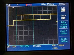
This next photo shows the time for a typical relay (Potter & Brumfield Tyco DPDT 12V coil, Digi Key part # PB384-ND) to react to a transistor switch, which simulates a microswitch that controls the coil current. Coil voltage was 12V as required by the relay design spec. The relay data sheet specifies under 10 msec for operation time, but this needs to be taken with a grain of salt as we shall see. The DigiKey catalog specs these times as 4.5 msec pull-in time (coil energized) and 1.5 msec release time (coil current interrupted).

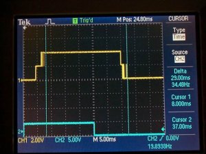
Starting again on the left, the blue trace at the bottom of the screen shows the drive to the switching transistor, and thus the drive to the relay coil (the transistor propagation delay is negligible on this time scale). The yellow trace indicates the relay contact moving between it's two positions exactly the same way the turnout points operate in the previous post.

We can see that yes, it does take 4.5 msec for the relay moving contact to pull away from it's initial position when the coil is energized (each dot of the graticule dotted squares represents 1 msec) by the horizontal yellow line becoming vertical at 4.5 'dots' to the right of where the blue trace rises at the far left. This is the important parameter - how long it takes for the relay contact to get to it's open position. The brief horizontal portion of yellow is the time for the relay moving contact to travel between its two opposed end contacts, just like the turnout points between the stock rails. The completion of it's operation is shown when the yellow horizontal trace reaches it's upper level, the fuzziness on this vertical edge is the 'contact bounce' period when the vibrating contacts steady down from their sudden movement.

Already we can see that if we throw the turnout manually as fast as possible at 3 msec, the delay in relay response will give us a short circuit for a period lasting 1.5 msec. Not good. Best to keep that finger on the points a little slower.

One way to speed up the relay pull-in time is with a higher voltage to the coil, which could overheat it unless a shorter duration higher voltage pulse (from a capacitive discharge unit) is used for initial fast operation followed by a 'holding' voltage within the relay coil limit. The higher speed travel of the moving contact will result in more contact bounce, but we don't care about that.

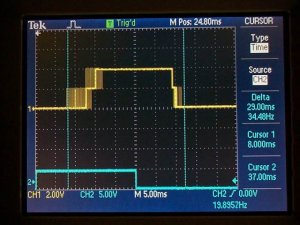
The real trouble comes at the center to right side of the photo. The relay coil drive current is switched off at the center of the screen as shown by the blue trace dropping back down to 0 volts (the lower position). It takes a whopping 9.7 msec for the spring-loaded relay contact to open again as shown on the yellow trace returning to it's vertical center - but this is not the fault of the relay itself. I have placed a silicon diode (1N4002) across (in parallel with and in the direction such that the diode is reverse biased from the power supply) the relay coil which drastically slows it down from the specified 1.5 msec. This time duration is well within the faster manual operation times of the turnout and can result in much longer short circuit duration even at normal manual turnout operating speed, and the several amps of current flow from the resulting momentary short circuit (the turnout points complete their travel before the relay contact opens) can severely reduce the life of the relay contacts. This is worsened by the fact that a microswitch mechanical linkage will be adjusted to throw the microswitch when the turnout points are at their physical center of travel, not when they first break contact with the stock rails. The delay is caused by the coil discharge current (the magnetic field slowly collapsing) through the diode.

The diode protects the switching transistor, and should always be there even if a microswitch is used instead of a transistor to switch the relay coil. When the current to a relay coil (or any other electromagnet) is suddenly switched off, the suddenly collapsing magnetic field tries to keep the current flowing. Since there is an open circuit to contend with (if no diode is there to provide a discharge path for this current), the voltage spike that occurs from the coil can be several hundreds or even thousands of volts! This will instantly kill a transistor, and will cause terrible arcing at the microswitch contacts, reducing their life drastically. For proof of this effect, connect a 1.5 volt battery to a coil (relay, transformer winding, turnout motor) and hold the two bare wires in your hand when you disconnect the battery. OUCH! :eek: Do NOT try this if you use a cardiovascular pacemaker, and use only ONE hand, not both so the voltage is not from arm to arm across your heart. Better yet, just take my word for it.

To return the relay release time to it's specified value, place a zener diode in series and back-to-back (banded end to banded end) with the regular diode across (parallel to) the relay coil. A zener diode works like a normal diode in one polarity, but when 'reverse-biased' against it's normal conduction direction will also switch on and conduct current once the applied voltage reaches the zener breakdown voltage. Zener diodes are available in many different voltage ratings, generally a 25-30 volt zener will fit within the typical 28 - 30 volts DC voltage rating of a microswitch. The coil-generated high voltage pulse will now be limited to the zener voltage, but the relay release time will be much faster, very close to it's specified time of 1.5 msec. Sorry, I don't have a photo of this yet.
 

Attachments

  • dcp04059 12v rly pb384-nd at 12v transistor driven 8ms pullin 12ms release.jpg
    dcp04059 12v rly pb384-nd at 12v transistor driven 8ms pullin 12ms release.jpg
    43.7 KB · Views: 273
Finally, here is the effect of driving the relay coil with too low a voltage, in this case 8 volts. The coil needs 12 volts to pull-in at it's specified time. As expected, the pull-in time (on the left) is much longer and very erratic, multiple exposures are shown.

Hope this info helps and is useful for anyone planning to use relays in conjunction with turnouts.
 

Attachments

  • dcp04060 12v rly pb384-nd at 8v transistor driven 17ms pullin 12 ms release.jpg
    dcp04060 12v rly pb384-nd at 8v transistor driven 17ms pullin 12 ms release.jpg
    43.9 KB · Views: 271

60103

Pooh Bah
Mar 25, 2002
4,754
0
36
Brampton, Ontario, Canada
Visit site
Glen:
This is fascinating. I don't understand half of it. :)
I assume that you're using new relays in good condition, not many-times-recycled, dusty old things from the telephone surplus shop?

Any comments about the suggestion of putting an automobile bulb in series with the frog wiring? would it react fast enough? Can we afford that many automobile bulbs?
 
Hi David,

Yes, brand new miniature relay with 3 amp contact rating, moving contact is lightweight for fast response. Telephone type relays have massive moving pieces in comparison and will be much slower.

The automobile bulb will help because of it's additional resistance even when cold, but can still allow lots of current to flow and wreak havoc on contacts that were not designed for these currents. Even fast overload-detecting electronic shutdown circuits don't help either; by the time the overload has been detected the switching damage has been done - the contacts go through a microscopic melting phase as the electric arc forms on break or make/break bounce. In some severe cases contacts can actually weld themselves closed. Choice is either light, fast responding contacts and avoidance of shorts, or massive contacts that can tolerate shorts.

Thanks for mentioning this in your earlier post, probably wouldn't have thought to dig into this effect otherwise. Currently use several microswitches together with a bellcrank from the throwbars, so no delay effects to worry about.

Regards,
 

Pitchwife

Dreamer
Apr 23, 2001
1,728
0
36
71
The middle of nowhere Oregon
Visit site
Hi Glen
I am very glad that this thread is here and that I read it. You brought up some very interesting points (OK, it's a pun :D ) that I had not considered while designing my layout. I have a bunch of 24 volt spring loaded solenoids that I plan to use as switch machines. They are rated 24vdc intermittant, but the catalog says that they can be used for longer duration at 12vdc. I had not taken into account the switching times of the points and the track power and the discharge voltage associated with them. I like your idea of using the zeners and will probably use them as a solution. A cheap but effective solution. Thanks for reminding me of this phenomenon and offering an effective remedy. Hopefully everyone who reads this (whether they understand it or not :eek: ) will take your advice to heart.
 
Hi Clark,

I like puns, have been know to make a few terrible ones.

Solenoids work very well for switch machines. I gather you intend to keep them powered at 12V to hold them in position? If so, a lot of them will put a fair drain on your power supply. Here's something to consider for latching without powering.

Many years ago i used solenoids scavenged from some old paper tape punch machines (really dating myself here). Linked them in pairs to make 2 coil machines, for latching mounted a large washer on the shafts with a bent springy wire (from a large paper clip) in a V shape bearing against the edge of the washer. As each solenoid was energized, the washer would slide past the point of the V in the spring wire, then the sides of the V held against the washer to hold the points latched. Worked nicely. A simpler method would use a V shaped spring wire in a way similar to to what Peco and MicrEngineering use now. You could also use permanent magnets to latch in either position.

Needed one last switch machine and ran out of solenoids. Rather than buy more, took an old fishing reel and an old motor from some toy that had been gathering dust in the junkbox. Linked the motor to the fishing reel and used the back and forth motion of that worm drive thing that guided the fishing line onto the spool as the turnout actuator, plus a couple microswitches to limit the travel. Maybe that was one of the first slow motion switch machines?

Anyway, using solenoids should let you connect heavy duty microswitches to the throwbar actuator instead of relays, so everything will always be in perfect sync and you won't need to worry about relay delay. Good luck and let us know how they work out.
 

Pitchwife

Dreamer
Apr 23, 2001
1,728
0
36
71
The middle of nowhere Oregon
Visit site
Hi Glen

Actually most of the solinoids will be used in the stageing yard and will be set up so that the only time they are powered is when that particular siding is in use. They have built in springs so when they are energized they pull the points one way and when the power is removed the return spring pushes the points back the other way.

As far as power, I used to do VCR repair and had junk boxes full of old machines that I could scavang parts from to give my customers the option of possably saving some money. When that industry disappeared due to the throw-away mentality of modern manufacturers I tossed them out, but before I did I went through each one and stripped all of the power supplies, transformers, motors, gears, belts, etc that I thought might be useful for my upcoming project. I want lots of animation besides the trains and so I have a lot of the materials I'll need to use for that. I could probably build a power supply for each individual application if I wanted to.

What I had originally intended was to use DPDT switches on the control panel, one side to switch the solonoids and the other to switch track power. What you were saying earlier about shorts made me start thinking about that kind of setup. I guess that what I could do would be to make all turnouts insulfrogs with a drop of shellac or paint which should hopefully make the switching time problem moot.

One other feature that I am incorporating is a tourist RR with an old steam enging and period cars. They will be running on a track with a reversing loop on either end. What will make this unique (at least I have never heard of it being handled this way) is that instead of reversing the polarity of the loops, I will be reversing the polarity of the main line while the loops retain their individual polarity. It works out on paper, I just hope that it works in real life. :)
 
I like that idea of using the spring return solenoids. You can still add the synchronized microswitch(s) as well with this method and not have to worry about power routing on the control panel. Adding more switching poles can give you reverse power routing in areas where it could be useful, where the turnout position selects which cab control powers the point end of the turnout. Shellac on the points could wear off in time and cause intermittant and hard-to-find headaches.

I do similar - never throw out a defunct device if it has transformers or motors etc in it. But rather than strip them down ahead of time, just pile them up in the attic till I need something out of them.

I have a concept design of a single track with reversing loops at each end similar to what you want to do. The main line reverses polarity based on turnout positions that change automatically with train detection on the loops, every second pass around each reverse loop is in the opposite direction to the previous trip. Never built it, but it seems to work on paper. Kind of a mechanical flip-flop. It's in TurboCad but discovered how to import it to MS Word, but not sure how to post it here. If you're interested I can email it, or if you can tell me how to post a MS Word diagram in this forum will be happy to do so.
 
give up with this attempted file conversion! Here's the text in a readable format to match the diagram.

Remember, I have not built this and there could be a bug lurking in there somewhere. If you plan on trying this, first analyze the operation carefully, if you find a problem let me know that i've goofed. Even if you don't plan to build it but want some mental fun, work out the logic and see if it really works.

This is an application that requires multipole switches linked to each turnout / switch motor which are driven by block occupancy detectors. The idea is for automatic reversing and opposite loop direction every trip. A folded dogbone is easier, but you won't get the opposite loop direction feature on each trip.


RULES

CW = clockwise
CCW = counterclockwise
N = North, NE = NorthEast etc

Four occupancy detectors SW, NW, NE, and SE trip adjacent turnouts to the occupied straight or diverging route. If these detectors are the infrared type they must be spaced greater than a train length apart. If current sensing type, the train cannot be longer than the loop length (obviously!).

Directions are controlled by turnout positions with a DPDT switch linked to one turnout throwbar, 4PDT linked to other.
Each loop and straight section have individual direction control. An additional pole may be required at each turnout for frog powering. Relays may be used instead.

Loop direction is controlled by the opposite loop turnout position.
When set to straight route, opposite loop is CW direction.
When set to diverging route, opposite loop is CCW direction.

When both turnouts are set to same route, either diverging
or straight, the straight section direction is from W to E.
When turnouts are set opposite to each other, straight
section direction is from E to W (XOR logic formed by cascading both turnout DPDT direction switches). One loop is tapped from the connection between the turnout DPDT switches, other loop has separate DPDT direction contacts on the opposite loop turnout, making 4PDT in all for that turnout.

Train direction on loops is automatically reversed every alternate trip.


OPERATION


1. Initial condition is both turnouts set for straight route. Eastbound train leaves CW west loop on straight,
NW occupancy detector maintains west turnout on straight,
train enters CW east loop on straight,
NE detector holds E turnout on straight.

2. When train hits SE detector, East turnout throws to diverging (SE) route, reverses straight section to westbound and west loop to CCW.
West turnout is still set to straight route.
As train hits NW detector, west turnout maintained on straight route.

3. When train hits SW detector, west turnout switched to diverging route,
reverses straight section to eastbound again, reverses east loop to CCW.
East turnout still in last position for diverging route, and is
maintained in diverging position as train passes SE detector.

4. When train hits NE detector, east turnout thrown to straight route,reversing straight section to westbound and west loop to CW.
West turnout still in last position for diverging route, and is
maintained in diverging position as train passes SW detector.

5. When train hits NW detector, west turnout thrown to straight route, reversing straight section to eastbound and east loop to CW.
This is the same as initial startup, cycle repeats endlessly.
 

Attachments

  • image002jpg.jpg
    image002jpg.jpg
    56.6 KB · Views: 102

Pitchwife

Dreamer
Apr 23, 2001
1,728
0
36
71
The middle of nowhere Oregon
Visit site
Actually what I had in mind was a little simpler. A train starts on the mainline in either direction.

When it is in the reversing loop a sensor reverses the polarity of the mainline while each loop retains it's own polarity. The black lines are the break points which isolate both rails. As the train approches the break point, the mainline track is already polorized so that it will continue on with no interuption of service.
 

Attachments

  • reversing_loops.jpg
    reversing_loops.jpg
    17.4 KB · Views: 94
Looks good, should work no problem. Do you plan to throw the turnouts manually or will the sensors throw them? If manual, you should be able to split the mainline into 2 separate blocks, each one direction controlled by it's turnout position and throwbar- linked relays or microswitches. Then you won't need the sensors. Just have to throw a turnout to the diverging route while the train is on its end loop to set the mainline polarity to the train coming off the loop. Then the second half of the mainline gets set to match polarity by throwing the opposite loop turnout to the straight route before the loco crosses the mainline mid gap.

Since this reversing function is not related to the points/frog switching, relay delay will not be an issue. Just be sure to wire the rails (not the power source) to the moving contacts of the DPDT switches to avoid any problem with different switching positions of the two halves of the DPDT switch function. ie if one switches before the other, all that happens is both rails are momentarily on the same power wire. But the other way around both power wires could get switched together (short circuit) if the two halves of the DPDT are not actuated at exactly the same time.
 

Pitchwife

Dreamer
Apr 23, 2001
1,728
0
36
71
The middle of nowhere Oregon
Visit site
As this is going to be a self-contained tourist RR. The sensors will trip the relays that will switch the points and the track polarity. In fact, Since I am planning this as more of an animation piece I have considered setting up sensors and controls so that after a push of a button the ride will start, make it's complete circuit and come to a halt back in front of the station/museum, ready for the next load of tourists. It wouldn't be that hard to set up controls that would handle everything, speed, sounds, whistles, etc...One thing I got from all those VCRs were a bunch of IR emitters and detectors. Just need to add some simple circuitry and it's ready to go. Be a nice backdrop to the business of running trains on the mainlines, interchanges, and swich yards.