Pantographs

Status
Not open for further replies.

Ray Marinaccio

Active Member
Aug 4, 2003
1,940
0
36
66
Dewey Az.
Visit site
In this thread I will demonstrate how I fabricated pantographs for a Pennline GG1.
The materials needed are:

.020" steel or brass wire
.010" brass sheet
1/2" length of 3/32" brass tubing
2 small springs


Materials for the jigs are:

a block of wood
straight pins
two 1/16" dia. roll pins (or 1/16" dia. rod)
1 popsicle stick


Tools needed:

needlenose pliers
fingernail clippers
soldering iron
solder
flux
small alligator clips
spring type clothes-pin
small file
ruler
pencil
scissors (to cut brass sheet)
tubing cutter (or razer saw)
1/16", 3/32", 1/8" drill bits and hand drill
small hammer
magnifier glass


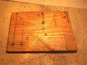
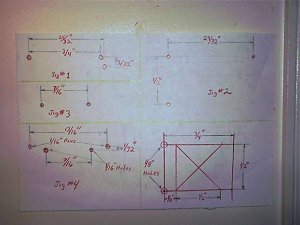
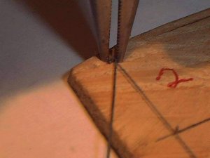
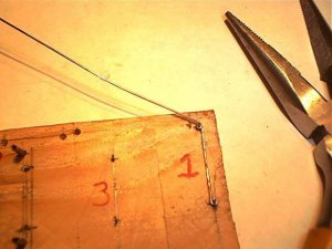
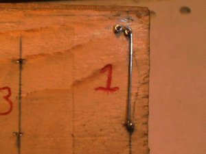
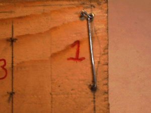
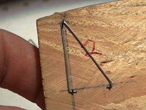
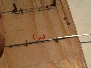
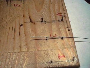
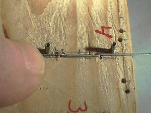
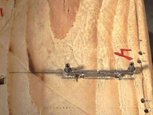
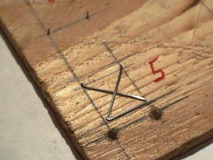
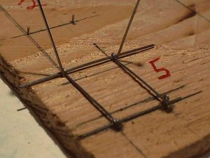
This is a photo of the jigs
 

Attachments

  • 1jig.jpg
    1jig.jpg
    53.4 KB · Views: 678

Ray Marinaccio

Active Member
Aug 4, 2003
1,940
0
36
66
Dewey Az.
Visit site
These are the dimentions for the jigs.
Jigs #1, #2, and #3 are made by driving straight pins into the wood at the possitions marked in the drawings and cutting off the heads.
Jig #4 is made by drilling four 1/16" holes at the dimentions shown and pressing 1/16" pins in the outer holes.
The drawing of jig #1 is backwards. Use the dimentions and build it as it is shown on the jig.
 

Attachments

  • 2 jig dimentions.jpg
    2 jig dimentions.jpg
    31.3 KB · Views: 593

Ray Marinaccio

Active Member
Aug 4, 2003
1,940
0
36
66
Dewey Az.
Visit site
Place the loop in jig #1 as shown with the arm on the left side of the bottom pin in the photo.
Then wrap it counterclockwise around the upper right pin.
Then counterclockwise around the upper left pin.
 

Attachments

  • 7 2nd loop.jpg
    7 2nd loop.jpg
    34.6 KB · Views: 562

Ray Marinaccio

Active Member
Aug 4, 2003
1,940
0
36
66
Dewey Az.
Visit site
Remove it from the jig.
You will notice that it will spring out of shape. You will need to bend it a bit untill it fits easily onto the jig.
I don't cut the part from the wire untill this is done, it's easier to handle.
 

Attachments

  • 8 3rd loop.jpg
    8 3rd loop.jpg
    17.8 KB · Views: 537

Ray Marinaccio

Active Member
Aug 4, 2003
1,940
0
36
66
Dewey Az.
Visit site
Once the part is cut from the wire I reinstall it on the jig and reshape the last loop.
This part will go on the left side of jig #5.
Two of these are required for each pantograph.
 

Attachments

  • 9 back on jig.jpg
    9 back on jig.jpg
    24.4 KB · Views: 530

Ray Marinaccio

Active Member
Aug 4, 2003
1,940
0
36
66
Dewey Az.
Visit site
The next part will basicly be the opposite of the first.
Start by forming the first loop as before.
Place it into jig #1 with the arm on the righthand side of the bottom pin.
Wrap it clockwise on the upper right pin.
Then counterclockwise on the upper left pin.
Complete the part as you did with the first one.
This part will go on the right side of jig #5.
Two of these are required for each pantograph.
 

Attachments

  • 91opposite side.jpg
    91opposite side.jpg
    25 KB · Views: 522

Ray Marinaccio

Active Member
Aug 4, 2003
1,940
0
36
66
Dewey Az.
Visit site
Form the loops on the ends as shown and cut the wires so they meet.
Two of these are required for each pantograph.
It is important that these two parts match perfectly.
 

Attachments

  • 97 using jig 4 2.jpg
    97 using jig 4 2.jpg
    43.8 KB · Views: 240

Ray Marinaccio

Active Member
Aug 4, 2003
1,940
0
36
66
Dewey Az.
Visit site
Clamp the bracket to a popsicle stick and solder it together.
Try to get the solder to flow into all the gaps.
I found that adding a peice of wire as a filler and lots of flux helps.
 

Attachments

  • 98 solder bracket.jpg
    98 solder bracket.jpg
    27.9 KB · Views: 250

Ray Marinaccio

Active Member
Aug 4, 2003
1,940
0
36
66
Dewey Az.
Visit site
The lower arm assembly will be fabricated in jig #5 by inserting two peices of wire through the arms fabricated earlier.
The equalizer lever of the arm on the left will be inserted into the hole in the jig.
The equalizer lever of the arm on the right will be pointing upward.
Use pins to hold the assembly in position.
 

Attachments

  • 992 using jig 5 1.jpg
    992 using jig 5 1.jpg
    39.3 KB · Views: 232
Status
Not open for further replies.