ORLIK BRDM-2 Build Report

Status
Not open for further replies.
Hi Gang!

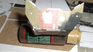
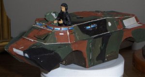
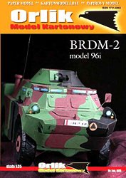
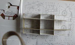
I am in the process of building the ORLIK BRDM-2 mod 96i wheeled recce vehicle as published in 1:35 scale. The ORLIK catalogue number is 005.

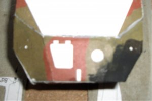
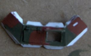
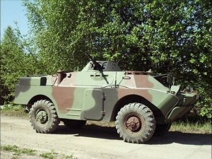
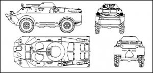
The vehicle as printed represents the Polish/Czech 96i variant of the Soviet BRDM 2 in Polish Army (WkP) service. Unlike the Soviet BRDM2, the 96i does not have "cross country belly wheels". Instead, there are large troop doors in the sides of the hull.

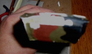
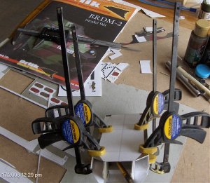
*20 Jan 08: I originally did not plan to paint this model. However, I also did not seal the model sheets before I started assembly, which I normally do.... . I got a rude shock when I sprayed my usual fixative coat after the hull was assembled. It dried completely white!! The can of fixative froze in my shop during a power failure. So, most of the model has, in fact, been painted.....

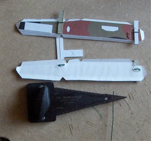
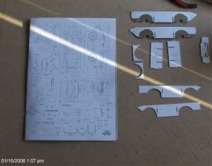
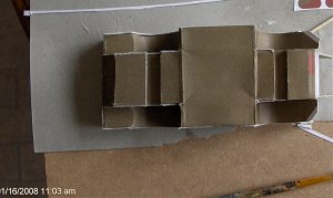
Do not figure upon slapping this model together in an evening. Consider this (at least) as a good 1:35 finescale plastic model and plan to work accordingly.

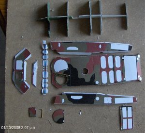
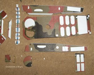
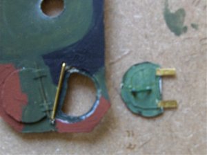
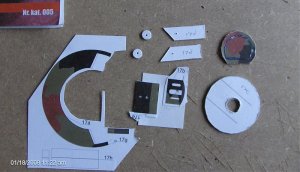
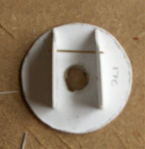
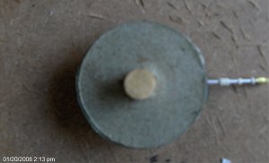
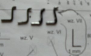
There are lots and lots of often-absurdly tiny parts to deal with here.

I previously did an overview of this kit. http://forum.zealot.com/t140061/

As I go along, I'll try to provide a set of comprehensive instructions and my building tips as no English instruction for this kit is available.

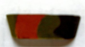
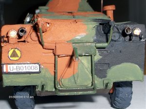
By the way: the cover illustration on the booklet appears to be of a a painted model. The camouflage pattern on the printed model appears to be standard NATO Pattern Woodland Camo, so the appropriate FS colours of whatever paints you use should suffice. (Light Olive Green, Red-Brown, Black)

Now, let us pray!

Jim
 

Attachments

  • ORKbrdm.jpg
    ORKbrdm.jpg
    18 KB · Views: 392
  • brdm2m96.jpg
    brdm2m96.jpg
    93.4 KB · Views: 17
  • BRDM 2 Line Dwg.jpg
    BRDM 2 Line Dwg.jpg
    38.6 KB · Views: 77

Dragos

Active Member
Jun 8, 2006
415
0
36
41
Romania
Hi Fishcarver, good luck with this one. I've build it last year and altrough it has some minors problems, the model turn out to be a nice one in the end.
I'm waiting to see the progress
 
Know this going in: this is a small-scale model which will require patience, planning and precise workmanship!!


After laminating the main structural parts to 1 mm (**) and 0.5mm (*) card, construction begins with the hull inside frames.

After cutting out the hull parts (1 a through f) dry-fit everything before gluing. Assemble the inside of the hull formers first and allow to dry thoroughly. IT IS VITAL THAT THIS ASSEMBLY BE KEPT SQUARE AS IT DRIES!!.

NOTES: a) Part number 1c (hull rear frame) on page 1 needs to be backed up with 1mm card.
b) Make an extra set of both parts 1e (page 1 ) and 1f (page 2) and back up with 1 mm card. These should be glued onto the inside of part 1a (around the wheel openings).
c).If you implement note b, above, it would also be useful to cut a spacer from 1 mm card and lay it flat across the top of the reinforced front wheel openings. This will help keep the frame square.
 

Attachments

  • BRDM Hull 1.jpg
    BRDM Hull 1.jpg
    145.9 KB · Views: 12
  • BRDM Hull 2.jpg
    BRDM Hull 2.jpg
    165 KB · Views: 18
Once this assembly is all squared up and dried, I would recommend installing the lower hull top (part 1d) to keep everything solidly together. If necessary, you can "weld" the top to the frames with glue from the inside.

Finally, attach the hull bottom skin (part #2). This is a fiddly job. I would first back part #2 up with plain paper, then cut it out. Prefold and dry-fit it.

*If I had this to do over again, I'd cut part #2 into 5 pieces: the center portion and the four wheel opening liners, and use joining strips to attach the wheel opening liners to the center section. It is a real pain in the fundus to attach part 2 otherwise..
 

Attachments

  • BRDM HULL Fit Part 2.jpg
    BRDM HULL Fit Part 2.jpg
    130.3 KB · Views: 13

josve

Senior Member
Oct 21, 2005
620
579
111
61
Odda Norway
Hello Jim!

Nice to see you build something on wheels again :)
That BRDM is kind of small eh? 1:35 isn't exactly big....
But if I know you right it will be a piece of cake!!
Looking forward to follow this build to the finishing line!
 
BRDM 2 Lower Hull Skins

Identify and prepare parts 3 (P&L), 4, 5, 6 (both P (Prawda = right) & L (Lewa=left) , and part 7. Parts 4 and 6 should be glued to ordinary paper before cutting out. Spot all holes on parts 5 and 6 with a pin for later drilling.

Dry-fit everything, then install in sequence parts 3, 4, 6, 5 and 7.

Any lack of squareness in the hull frames will now appear, especially around the fitting of parts #6. Work carefully. Once everthing is in place, allow to dry thoroughly. After drying, you can trim off any "naughty bits".

Next step will be building of the upper hull structure.
 

Attachments

  • BRDM Lower Hull Front 1.jpg
    BRDM Lower Hull Front 1.jpg
    117.9 KB · Views: 11
  • BRDM Lower Hull Front 2.jpg
    BRDM Lower Hull Front 2.jpg
    72.4 KB · Views: 9
  • BRDM Lower Hull Front 3.jpg
    BRDM Lower Hull Front 3.jpg
    61.3 KB · Views: 64
BRDM2 Upper Hull Step 1

This step involves preparation of the frame parts 8 and 8(a),8(b) and 8(c).

I added an extra former (clone of part 8(a) just in front of the turret location.

All parts numbered 8 should have been laminated to 1.0 (**) card.

The other parts needed are parts 9 (p & l ), 10, 11, 11a and 12.

Parts 9 (both), and 12 should be backed up onto plain paper.

Yes! I am going to open a couple of hatches!! So the first Part 8(a) needed to be notched accordingly.
 

Attachments

  • BRDM2 Upper Hull Parts 1a.jpg
    BRDM2 Upper Hull Parts 1a.jpg
    174.2 KB · Views: 49
  • BRDM2 Upper Hull Parts 1.jpg
    BRDM2 Upper Hull Parts 1.jpg
    211.3 KB · Views: 24
Upper Hull Assembly Part 2

IT IS VERY IMPORTANT that you PLAN AHEAD, prepare all of the parts first, (drill, score, etc AND DRY FIT EVERYTHING before assembling the upper hull skins to the frame. (the top picture in this set shows the wire grab handles being installed before assembling the upper hull)

For example: the glue tabs on Parts #9 need to be made a little wider.(I widened BOTH the top AND bottom glue tabs).

When this is done, the bottom tabs need to be notched to fit around the bottom of the frame formers. This will make it easier to snug averything down when mating the upper hull with the lower.

Note also that Part 10 (the upper hull top deck) needs to be lightly scored along the faint lines just behind the front hatches and just behind the turret location to conform to the backward slope of the top deck.

I added a driver's side windscreen and operable hatch, and an operable hatch on the left side of the roof. The roof hatch required some modification to the front frame crossmember

Assembly should be approached as follows:

1. Glue the upper hull frame in postion to the lower hull top. MAKE SURE THAT THE FORMERS ARE SQUARED UP WITH THE GUIDE LINES!!

2. Assemble the rearmost portion of parts 9 (left and right) to the rearmost portion of the upper hull top first. Apply the upper glue tabs of Parts 9 to the underside of Part 10. Align carefully and allow to dry.

3. Glue the tabs at the extreme rear of parts 9 to the rearmost frame former, then glue the rear flap of Part 10 into place. Again, allow to dry thoroughly.

4. Work forward in sections, joining Parts 9 to part 10 as you go forward. As each section is aligned and set up, allow the whole assembly to dry.

5. glue the frame to the inside of parts 9 and 10, and glue the bottom tabs of parts 9 to the lower hull. Again, work in sections from the back to ensure proper alignment. Any gaps around the junction of the upper and lower hulls can be "welded" with white glue and touched up later.

5. Attach Part #12 to the front of the frame, and to the front edge pf parts #9.

6. Attach Part 11A to part 12 and allow everthing to dry thoroughly!

7. CAREFULLY install the Vision Port Strip ( part 11). This is a fiddly job, fiddly, but my Part 11 fit like a champ. Provided you've done a clean job to this point, you should have no problems. I'd recommend starting at the back of one of the sides and working around, applying glue to one set of tabs on part 11 at a time, noodling it into place and going on to the next A needle or a fine awl (for moving the part) and a small brush (for glue application) is useful here.


The bottom photo shows the completed hull with "white glue welding" completed.
 

Attachments

  • BRDM2 Upper Hull Wire Parts.jpg
    BRDM2 Upper Hull Wire Parts.jpg
    159.9 KB · Views: 13
  • Upper Hull Front.jpg
    Upper Hull Front.jpg
    104.5 KB · Views: 10
  • Upper Hull Hatch 1.jpg
    Upper Hull Hatch 1.jpg
    134.6 KB · Views: 32
  • Upper Hull Assembled.jpg
    Upper Hull Assembled.jpg
    106.2 KB · Views: 12
BRDM 2 Turret Assembly

Again, prepare all parts before assembly. I backed all single-thickness card parts with plain paper. Prepare the wire parts for the heavy Machine Gun and the 7.62 coaxial MG. I used 1/16 inch aluminum tubing.

I used brass eye pins for the turret lift rings, following the principle of "close enough for government work"....... The flash eliminator (part # 18 ) was made from a piece of .005 brass sheet, and I replaced all of the other 18-series (HMG detail) parts with strips of masking tape.

Part 17g (the sight aperture) is an ABSURDLY tiny part. I did manage to cut it out and install it, but next time I'll just cut down a sequin pin and stick it in there.


I tried to get fancy and open a hatch in the top of the turret, forgetting to check reference materials (the BRDM 2 does not have a turret hatch). In any case, I screwed up the kit part for the turret top (# 17) and had to scratch-build a new one. Ahem.

Part 17 should fit INSIDE the turret shell (17 a) and be flush with the top inside edge. Dry-fitting is important here. If trimming is necessary, trim the turret top.

TRIPLE-layer the gun mantlet ( 17b) and the gun mounting (17 e) on scrap cardstock from the booklet.

Before the glue dries on the laminations on part 17e, roll it around a dowel or other cylindrical object of the approximate diameter of part 17 f (formers/support for gun mount) and allow it to dry. Then drill the holes in part 17 e and test-fit both machine guns before assembling.

Start with the turret inside frame (17 c and d). I used a piece of 3/8" dowel for the axis.

Parts 17 f are the ends of the gun mount. I used a piece of 1/16 (1.5 mm) brass wire in place of the 0.5 mm recommended for "Wz 1."

The reat of the assembly is pretty straightforward........
 

Attachments

  • BRDM Turret 1.jpg
    BRDM Turret 1.jpg
    150.3 KB · Views: 8
  • BRDM Turret 2 dry fit.jpg
    BRDM Turret 2 dry fit.jpg
    102.6 KB · Views: 8
  • brdm turret 3d.jpg
    brdm turret 3d.jpg
    94.5 KB · Views: 66
  • BRDM Turett 3e..jpg
    BRDM Turett 3e..jpg
    123.3 KB · Views: 9
  • Turret 4.jpg
    Turret 4.jpg
    70.7 KB · Views: 59
Suspension, Wheels and Tires.....

Nothing too wacky here, just lots and lots of parts to cut out and assemble-over and over again.

Build the axle housings and springs and install these parts to the hull. The offset differential (parts series 30 a, b. c and d) goes to the front.

I used tiny basswood blocks in place of the spring mountings parts 36 and 37.

Part series 46 is for the spare tire.
 

Attachments

  • BRDM Wheels And Tires 1.jpg
    BRDM Wheels And Tires 1.jpg
    210.3 KB · Views: 11
  • BRDM Wheels And Tires 2.jpg
    BRDM Wheels And Tires 2.jpg
    215.7 KB · Views: 13
Front Trim Vane

The front trim vane consists of part number 26 (inner and outer) and four 1-mm wire parts "Wz VII"

The mounting points for these wire parts are indicated on both the hull and part #26. I had drilled the mounting holes in the lower hull ( parts #6) before assembling the lower hull skins, and reinforced the area around these holes with cyanoacylate glue.

The short part of the right-angle bend in Wz VII is intended to fit into the hull, with part #26 attached to the longer end of Wz VII.

However, there is no indication given as to HOW "Wz VII" is to be attached to part 26.

The widest part of part 26 is the top. (first photo). I added a third layer of card to the part.

Part 26 needs to be shaped to fit around the front profile of the hull with a rounded right-angle bend as shown in the second photo, which is a view looking down.

I used cyanoacrylate glue to attach 1/8" pieces of styrene tube over the locations indicated for the mounting points on the inside of part 26, after shaping it. (third photo)

The templates given for WZ VII are the right length. I made these parts out of 1 mm mild steel florist's wire, and put a 90 degree bend in 1/8 " from the end (fourth photo).

Place the wire parts in the hull holes first but do not glue. With a bit of careful fiddling, Part 26 can be clipped into place. (last photo)
 

Attachments

  • BRDM 2  Part 26 a.jpg
    BRDM 2 Part 26 a.jpg
    123.2 KB · Views: 55
  • BRDM 2 Part 26 b top view.jpg
    BRDM 2 Part 26 b top view.jpg
    48.5 KB · Views: 10
  • BRDM 2 Part 26 Right inside.jpg
    BRDM 2 Part 26 Right inside.jpg
    61.8 KB · Views: 8
  • BRDM 2  Part 26 Wz VII.jpg
    BRDM 2 Part 26 Wz VII.jpg
    70.9 KB · Views: 6
  • BRDM 2  Part 26  installed side.jpg
    BRDM 2 Part 26 installed side.jpg
    68.8 KB · Views: 76
Rear Tire Carrier

Fortunately for all of you, I somehow managed to lose the series of pictures that depicted the fabrication and installation of a host of small detail parts such as mufflers, exhaust pipes, lights, mirrors, tow hooks, etc.

When working with such parts, the trick is knowing when to stop and take a break! ( just like when you are hitting yourself over the head with a board..... :)

The last detail to be fabricated is the REAR SPARE TIRE CARRIER.

The card parts required for this step are at the bottom corner of page 3 of the booklet, and are numbered 42 (L & P), 43, 44 (L & P), 44 a (L & P), 44 b and 45.

Four wire parts are required. Templates are provided for 3 of these, marked Wz X, XI, and XII. **You will also need a straight piece of wire 1 mm in diameter and approximately 3/4 inch ( 18 mm) long. This wire is not shown either on the templates or in the illustration "Rys. 9".**

I puzzled over thie assembly of this contraption for quite awhile, and then I figured it out. Here is how I did it:

1. Renumber part 44 (L and P) as "43a (L&P) (these are the solid brown and black strips)

2. Renumber part 44a (L & P) and 44 b as "42a (L&P)" and "42 b" respectively.

3. Centre Wz XI at the bottom of the rear side of the hull. Drill two holes and attach Wz XI to the hull.

4. Back Part 43 with plain paper. Drill out the hole in the centre to 1 mm. Fold it carefully along the indicated lines so as to get nice, sharp right-angled corners. Then saturate it with cyanoacrylate (CA) glue and allow it to dry thoroughly. Install the 3/4" (18-mm) straight wire through the hole in the middle of the long side of part 43.

4. Prepare parts 42 by drilling out the holes and carefully folding it along the indicated fold lines (Yes, they are there!!) to obtain a four sided tapering structure. Make sure to put the notch in the narrow end. Saturate these parts too with CA glue and allow to dry.

5. Prepare the triangular parts "42a (L & P) " by gluing them to "42 b". Then glue these assemblies to parts 42.

6. Glue the short sides of Part 43 across the open ends of wire part Wz XII.

7. Place part 43 over the long side of Wz X , with the previously attached Wz XII to the bottom. Centrer Part 43 on Wx X and wrap parts "43a" around Wz X on either side. ( I used masking tape instead!)

8. Glue the ends of Wz X into the notches in parts 42.

9 Then, attach parts 42 to the hull. If you have done this properly, the bottom edge of Wz XII should rest on Wz XI.

10. Prepare part 45 by punching out the 3 larger holes and drilling a 1 mm hole in the centre. Glue part 45 across the opening of the spare tire. Mount the spare tire on the wire projecting from Part 43.

I have attached a diagram which I hope will make all of this clear!!

The photos show what you should have when you are done.
 

Attachments

  • BRDM 2 Tire Carrier.jpg
    BRDM 2 Tire Carrier.jpg
    42.6 KB · Views: 11
  • BRDM 2 Rear.jpg
    BRDM 2 Rear.jpg
    146.1 KB · Views: 69
  • BRDM 2 TIRE  Carrier Bare.jpg
    BRDM 2 TIRE Carrier Bare.jpg
    198.3 KB · Views: 64
Status
Not open for further replies.