New toys - pieces of a puzzle?

Arlaghan

Member
Sep 9, 2003
658
0
16
50
S. FL
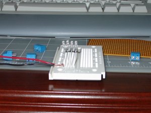
Went to radio smack yesterday to pick up some thinner awg wire (been using 20 awg and you saw how bulky it was in the gas station) and thumbed through their electronics selection. I was looking for a "modular" means to wire my structures (as opposed to using tape and pressing stuff with my fingers!) and came across this neat stuff: Bread Board, Perforated Board, and these clip thingies with screws for tightening wires that can be "plugged" into the bread board or soldered onto the perf board. I bought them without really having a plan...

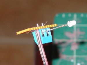
Now... to put the pieces of the puzzle together... My idea now is to solder blue clips to a small piece of the perf board and then securely attach this to the bottom of the structure (screws and/or glue). I can then have all the leads for my light bulbs screwed in the blue clips - making it easy to change them out, should I need to later on. Then have a feeder come off my "circuit board" ending with a female plug and the corresponding male plug on the layout. This way, I can interchange structures from say a permanent layout to an NTRAK module or vice versa! :D

Anyway this got me thinking... any neat "inventions" out there that you've done in the past, or are thinking of doing on any project that you'd like to share? I'm looking for innovative ways to solve problems. ;)
 

Attachments

  • untitled-1.jpg
    untitled-1.jpg
    64.8 KB · Views: 179

guppyman

Member
Dec 6, 2001
114
0
16
51
League City TX
www.railimages.com
Ya know, I have quite a few breadboards left over from when I went through electronics classes....

They keep popping into my mind while daydreaming about building my perfect layout.

Keep us updated on what you do with them.
 

artur_p

New Member
Dec 24, 2003
17
0
1
Visit site
In Mississauga on Dixie and Matheson there is a plaza with only electronic stores, you can get any electronic part you want. radio shop will only rip you off.
 

Arlaghan

Member
Sep 9, 2003
658
0
16
50
S. FL
Well, I have successfully fried one of those LEDs tonight!

Lesson learned? NEVER pump 15 volts through your LEDs unless you like to see it flare up inside and reek of smoke! :eek:ops: :rolleyes: :p
 

Arlaghan

Member
Sep 9, 2003
658
0
16
50
S. FL
WIRING GIZMO

I've created this little aparatus for my structures. After some experimentation (and phone consultations with my brother, Mr. Physics) I've come up with this "modular" way to wire my lighting. The contraption consists of one of the blue clips with one lead connected to the feeder lead and the other connected to a 470 ohm resister, which in turn is connected to the opposite feeder lead. The blue clip thingy allows me to screw in all my LED feeders in parallel, putting them all in series with a single resister - enabling me to pump 12 volts (a better standard, I feel) universally across all my structures - they each take what they need, the resister takes the rest. I just need to solder the connections, screw this onto the bottom of my structure, and plug in my lights.
 

Attachments

  • wiring-gizmo-1.jpg
    wiring-gizmo-1.jpg
    57 KB · Views: 86

Racharg

New Member
Oct 24, 2003
43
0
6
Ontario, Canada
Visit site
Mat: Guelph's not that far from you, there's Neutron Electonics on Woodlawn road. There's also an army surplus store in Kitchener that's great for electronics. Found cheap relays there to make my DC throttles with.
 

Racharg

New Member
Oct 24, 2003
43
0
6
Ontario, Canada
Visit site
Arl:

That's awedsome. I'm in need of something similar, next time your talking to your brother, could you ask him whether a similar set up would work for 1.5V grain of rice bulbs and what value resistor I might use?
 

Arlaghan

Member
Sep 9, 2003
658
0
16
50
S. FL
Originally posted by Racharg
Arl:

That's awedsome. I'm in need of something similar, next time your talking to your brother, could you ask him whether a similar set up would work for 1.5V grain of rice bulbs and what value resistor I might use?

Racharg,

This is something I can help you with. I searched on google, and came across a calculator for resistance for LEDs, but doing the math myself, I got the same answer... here's what I assumed and what I came out with:

In electronics there is a basic formula for DC currents:

V = IR

V = Voltage
I = Current
R = Resistance

Now, if you are supplying 12 volts from your transformer (as I am) then all the voltages in series need to add up to 12. So, if your light bulb uses 1.5, then the resistor needs to account for 10.5 volts. I don't know what bulbs you are using, but mine are rated for 15 mA (or 0.015 Amps), which is the current.

Plugging in the values you get:

10.5 = 0.015 R

R = 700 ohms

That's the resistor rating you would need to wire up a single bulb. (Just got off the phone with my brother - he confirms all of this :) ) Hope this is helpful to you... if you have different bulbs, just substitute your values and you can easily find out what resister you need.