Need Help with Atlas controller #220

davera

New Member
Jul 8, 2004
18
0
1
57
www.ofoto.com
I am having problems with my layout when hooking in an Atlas Controller (#220) to control a turntable.

According to the Atlas wiring book, the common rail needs to come of the controller "C" terminal. I did that and my trains do not operate. If I take the "C" off the two cabs (soldered together), the trains do operate but the controller needs to be in a specific (presumably off) position. I can then use the reverse switch on the cabs and the locos does reverse correctly.

Again, according to the Atlas book, when you do use a controller, you should not use the reverse switches on the cabs but rather the reverse sliders on the controller, one for Cab A and one for Cab B

It seems like I have some type of short or perhaps a faulty controller.

This is for my main line, where I guess I could avoid the controller entirely since it is just for the motor of the turntable. But when I get to my yard, I have 2 reversing sections, for which I believe I will need the controller. And hance even greater concern.

Anyone care to offer suggestions or tips?

Thanks
 

Tad

Member
Apr 8, 2003
273
0
16
60
Boise, Idaho
Visit site
First of all, a few questions.

Are the power packs only connected to the Controller?

Are the positive and negative leads from both of your power packs both connected to the Controller at the appropriate location for Cab A & B?

Is the Controller the first switch that is hooked to the power packs?

Do you have X & Y on the Controller wired to the two rails of the reversing section? In this case that would be the turntable bridge track.
 

davera

New Member
Jul 8, 2004
18
0
1
57
www.ofoto.com
answers to questions

Power pack A is connected directly to the controller
power pack B has one wire connected to the controller and another wire connected to a series of selectors that have all been connected together and to the controller via spade connectors (this connects to the second terminal for the power pack on the controller).

The positive and negative leads are both connected (one indirectly) to the terminals on the controller

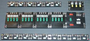
The controller is not the first device connected to the power packs. It is for 3 of the 4 wires coming from the power packs. The 4th wire first connects to 4 selectors and then connects to the power pack. See the attachments on this thread for picture of the control panel


The X & Y are wired to the motor terminals that drives the turntable. I have the turntable bridge track connected to the same selector as the track that leads up to the turntable (same block). I am using an Atlas turntable. Could this be the problem? Based upon everything I have seen only the motor was supposed to be connected to X and Y, to turn the turntable clockwise and anticlockwise. the bridge track has been shown to be connected in parallel to usually the lead up track.
 

Attachments

  • IMG_0152a.jpg
    IMG_0152a.jpg
    27.7 KB · Views: 204
  • IMG_0155a.jpg
    IMG_0155a.jpg
    15.5 KB · Views: 200

Tad

Member
Apr 8, 2003
273
0
16
60
Boise, Idaho
Visit site
If you are using the Controller to control the turntable drive you are correct in connecting the X & Y from the Controller to the X & Y on the turntable.

There appears to be three problems with your wiring.

First, both of the positive and negative leads from both of the powerpacks need to be connected to the Controller.

Second, the turntable bridge should be wired as a seperate block from the turntable lead, any stall tracks and any other blocks on your layout.

Please refer to the Complete Atlas Wiring Book. The diagram in my 2000 version is on pg. 53, Figure 7-7.

Third is probably how you have your common grounds connected. There should be only one common ground connection to any of the Atlas wiring components that you are using. This should be connected to the C connection on the Controller. If you are using multiple Controllers it should be connected to the C connection of furtherest Controller that is ganged from your powerpacks.

Please refer to the Complete Atlas Wiring Book. The diagram in my 2000 version is on pg. 16, Figure 2-11.

If you have multiple ground connections, such as to blocks on the layout and the turntable, a way to wire that that you should considered is this.

Bring all common ground connections to one side of a terminal strip.

TerminalStrip.jpg

Cat # 274-670 at Radio Shack, $2.49 each.

Connect the terminals on the other side of the terminal strip using a jumper strip.

Jumper.jpg

Cat # 274-650 at Radio Shack, $1.99 each.

If you have more than eight common ground connections,this might be the case if you gapped both rails instead of one. I did this. You can gang the jumper strip side of the terminal blocks by uisng an additional terminal strip cut to fit or using a wire to connect the jumper strip sides of the terminal strips.

Bring one wire from the jumper side of the terminal strip to the C connection on the Controller.

I think if you wire it in this manner, it will fix your problems. Let me know this helps.
 

davera

New Member
Jul 8, 2004
18
0
1
57
www.ofoto.com
Clarification

Firstly, Tad, thanks for taking the time to help me through this. This is why I love the Gauge forum.

One comment regarding common rails. What I had done was solder nearby common grounds and then brought a single conductor to another meeting point, where I again soldered the conductors, until ultimately I had one common conductor soldered to the appropriate C conductor on the connector (I used parallel computer cable with 25-way connectors. What you are suggesting, if I understand correctly is to home run all common conductors to the terminal strip(s)?

I will connect both conductors from both cabs to the controller and not as I have now.

The stall tracks are controlled by the connector. there are 3. I can replace this with a selector and then provide the extra block for the turntable bridge. The reason I had the turntable bridge connected to the approach track was because of what I saw in fig 7.4. But maybe that only applies to single cab operation?

Is the purpose of the jumper to short the 2nd side of the terminal stip, so that all 8 wires on the one side of the terminal strip are now connected together to one conductor going out of the terminal strip? (btw, radio shack is much cheaper than Home Depot when it comes to these terminal strips. I paid $8 each at HD!

thanks
 

Tad

Member
Apr 8, 2003
273
0
16
60
Boise, Idaho
Visit site
You're welcome.

Figure 7-4 is for a manual drive turntable with single powerpack.

Soldering the common grounds into a common circuit will work, too. I gapped both rails and wired my layout, as I explained, with all grounds running to the terminal strips so that if I wanted to go DCC in the future, I wouldn't have to rewire the whole layout to do it.

Yes, the jumper strip serves the same purpose as soldering all of the common ground connections into one circuit. It links them all together so that you can connect one ground wire to the C connection. Your way works just as well as long as the common is connected in the right place.
 

davera

New Member
Jul 8, 2004
18
0
1
57
www.ofoto.com
Radio Shack

Tad:

I just went out and got the terminal joiners and jumper strips. It looks like a nice neat way to do it. I will probably try to locate them in 2 central areas beneath the layout to avoid long wire runs.

This is all starting to make sense now...

I will give it a bash this weekend.

Thanks again for the advice

David
 

Ralph

Remember...it's for fun!
Jun 18, 2002
5,134
0
36
64
St. Paul, MN
Visit site
Guys, this is an excellent thread! Nice use of photos for clarification. I saw this thread yesterday and tried to find my Atlas Wiring book. I found it today but I see things are well under hand! :)
Ralph
 

davera

New Member
Jul 8, 2004
18
0
1
57
www.ofoto.com
still not working

ok. i corrected the incorrect wiring so that now both wires from both cabs connect to the controller directly.

it still does not work.

i then disconnected the block that connects to the turntable bridge track, as all i want to do right now is see the rest of the layout work. i can deal with the turntable bridge track later. beneath the layout i did disconnect the bridge track from the lead up track per Tad's earlier observation.

still did not work.

i then figured lets try isolate the problem. i disconnected the control panel from the layout, to see if the problem is in the control panel, remembering that everything worked fine before i introduced the controller, ie the loco worked fine on the layout, i could control it with either cab a or b. the direction was controlled by using the cab reversing switches..

i then tried to measure potential difference across the different terminals of the controller to get a better understanding of how it works... but no luck.

i then tried a spare controller just by connecting the leads from 2 cabs to the appropriate terminals. as a test, i measured the voltage across the XY terminals and did not notice any potential difference, no matter what position the sliders (cab selection for the XY section and direction of XY section) was in. i was expecting to see a positive/negative voltage drop when the direction was to the left and the inverse when it was in the right position. yet all i saw was +0 or -0. do i have a defective controller?

your help would be much appreciated

Perhaps another question is worth asking. I have connected the power packs to the terminals on the RIGHT of the controller. I just looked through every layout book that I have that uses Atlas components and the cabs always connect to the controller on the LEFT terminals. I am wondering if perhaps, even though it has never been explicitly stated that the terminals are not symmetrical and that you must connect the cabs to the LEFT terminals and then the rest of components to the RIGHT terminals???
 

Tad

Member
Apr 8, 2003
273
0
16
60
Boise, Idaho
Visit site
David,

That is the problem. The Controller must be on the left side of your control panel. If you look at Figure 2-9 on page 16 of The Complete Atlas Wiring Book, you will see a circuit diagram of the Controller and see why.

I'm sorry I didn't catch this earlier, but when I first replied to you, I didn't see your picture of your control panel. You did a nice job on the panel, but you need to bring the power in on the left side and move your Controller to the other end.
 

davera

New Member
Jul 8, 2004
18
0
1
57
www.ofoto.com
Yep, when i carefully read the electrical schematic of the controller, the left and right terminals are NOT symmetrical. the left are inputs and the right are outputs. If I was at Atlas, I might have labeled these as such to avoid this type of problem. There is not a single note anywhere that indicates this other than the implied arrangement from all their diagrams...

thanks again for the help. it all works now..