N scale Peco switch frustrations...

TrainNut

Ditat Deus
Sep 15, 2004
1,731
0
36
54
AZ
Heya all,
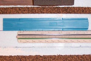
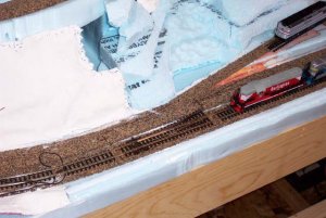
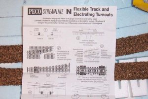
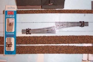
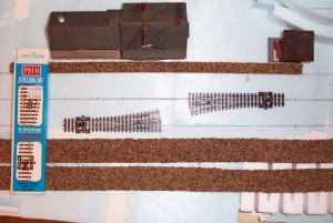
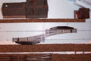
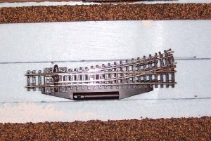
I picked up some Peco Streamline Universal medium switches today. My LHS said PECO was the best so I went that route. However, I get home and am trying to sketch out a simple passing crossover onto my foam and have come up with some complications. According to the instructions in step 2 (picture 1), you simply butt them up end to end and your done. The Kato track spacing guide recommends ideal track centerline spacing to be 1-5/16"s apart as measured by my black lines drawn on the blue foam. If I do this according to the Peco instructions, I only get 1-1/16"s apart (picture 2). Yes, I know that one of the switches is upside down...for layout purposes, that should not matter. If I move them to the correct centerline spacing apart, I end up with this big old gap in between them that is going to have to be filled by a little tiny piece of filler track - what a pain (picture 3). My older Atlas switches don't have this problem (picture 4) because they have a slighly tigher radius and a slightly longer track that you can just barely make out in picture 5 when I overlay one on top of the other.

I don't want to use the Atlas switches but I will if I have to in order to get around this problem. Does Peco make a little filler piece of track to compensate for this or what's the deal? Anybody else come across this and how did you fix it?
 

Attachments

  • Picture 1.jpg
    Picture 1.jpg
    60.5 KB · Views: 409
  • Picture 2.jpg
    Picture 2.jpg
    61.6 KB · Views: 411
  • Picture 3.jpg
    Picture 3.jpg
    59 KB · Views: 430
  • Picture 4.jpg
    Picture 4.jpg
    60.7 KB · Views: 403
  • Overlapping switches.jpg
    Overlapping switches.jpg
    63.5 KB · Views: 407

TrainNut

Ditat Deus
Sep 15, 2004
1,731
0
36
54
AZ
Sooo, then what's up with Kato? Is the centerline spacing for Japan different than the U.S.? Here in this picture you can see the Kato re-railer/track spacer guide and it shows the spacing to be 1-5/16". Hmmmmm, I already layed down a bunch of cork with that spacing. Anyone else?
 

Attachments

  • DCP_4427 copy.jpg
    DCP_4427 copy.jpg
    62 KB · Views: 391

inkaneer

New Member
Jul 7, 2001
63
0
6
Visit site
I do not think there is a standard track spacing. Even the real RR have increased their spacing to where they are now 20 feet apart. That equates to the same spacing as Ntrak. Previously 14 feet was typical then with more "high and wide" loads a 16 foot spacing was employed. Now with traffic condensed and better traffic control many mailines are reducing adjacent tracks from 3 to two and increasing the spacing to 20 feeet to provide an extra margin of safety for track crews. So you may have to use that short filler seciton of track between turnouts.
 

Meiriongwril

Member
Mar 1, 2006
183
0
16
Lafayette, Lousiana
Remember that Peco is based on British practice, and the loading gauge (both height and width) is smaller. In the UK a spacing of 14 feet would be quite usual (except in the old Great Western area where many lines were originally broad gauge [7'0.25"] which, after narrowing, left a wider space between lines).
That is why, also, Peco tie arrangements and turnout shapes etc don't quite match US prototypes.
 

engineshop

Member
Apr 29, 2003
136
0
16
61
San Rafael, CA USA
www.engineshop.org
Peco like other European track manufactures use 33,3 mm spacing between two tracks as started by Arnold. I assume you use track spacing recommended by NMRA which did not adapt Arnold's spacing.
I have all peco with 33.3 mm spacing and I am happy.
 

pgandw

Active Member
Jul 9, 2005
1,002
0
36
Different track manufacturers use different track geometries. The Peco turnouts (switches) actually give you more flexibility because you can use narrower spacing if you choose.

You have identified the solution - cut a small filler piece from a piece of flex track. Flex track is perfect for this type of situation because, if need be, you can curve it to any practical radius to fit. Cutting flex track with special purpose rail nippers is fast and easy. Just don't use your rail nippers for anything else. A quick touch or two with a file to ensure smooth transistion from rail to rail, and your trackwork woes are minimal.

The varying geometries are also the reason it is important to have good track libraries in your track planning software. Or use accurate templates when drawing by hand. And by all means, lay things out full size, as you have done, before fastening anything down permanently.

my thoughts, your choices
 

TrainNut

Ditat Deus
Sep 15, 2004
1,731
0
36
54
AZ
Help! Who can lend some electrical savy?

Okay so the saga continues. I now have one continuous loop laid all the way around the layout. I have two of these Peco electro frog switches hooked into the mainline for future track connections but not connected at the moment. I am testing the loop using a DC controller wired in with gator clips to one set of feeds just to the left of the switch in the picture. The train is running around just fine UNTIL I throw one of the turnouts to a position other than straight ahead. At that point, everything comes to a halt 'though I do not get the dreaded red, dead short light. I got to reading the instructions and it comes up with all this nonsense about adding plastic insulators here and there in order to make things work but never seems to say why.

Can someone help me to understand why everything is coming to a halt when I throw the switch?
 

Attachments

  • DCP_4515.jpg
    DCP_4515.jpg
    62 KB · Views: 244
Hi, TrainNut:wave:
www.the-gauge.com/showthread.php?p=6324
www.the-gauge.com/showthread.php?p=192421

The PECO Electro-frogs are power-routing. The rails which the points are hinged get
power from the contact between the points and the rails. So, the frog and the rails
passing through it are both the same polarity and will change polarity when the turnout is switched.
Therefore, the rails to the right of your turnout in the photo will not have power across
them when the turnout is switched to divert. If you want those rails to stay powered when
the turnout is switched, you need another feeder on the right side. A feeder on the
spur is also required. You also need an insulated gap on all four rails leaving the turnout
on the right side to prevent a short circuit when the turnout is switched.

Someone else may have a clearer description, so please chip in!!:) :)
 

pgandw

Active Member
Jul 9, 2005
1,002
0
36
As Sid Chase said, you have power routing turnouts.

If I understand your situation correctly, you have a continuous loop with no insulating rail joiners or gaps cut, and the Peco Electrofrog turnout installed. If all this is true, you should be getting a short circuit in addition to shutting the main line down when you throw the turnout to the curved direction. If you are not getting a short, you probably have a poor electrical connection at one of the track joints, at least poor enough to restrict current flow and cause the short circuit light not to come on.

The 1st diagram (taken from Proto87 Stores web site, animation removed) shows your turnout in the straight position.
View attachment 32380

Note that power flows normally on the straight portion, but there is no power to the curved section - both rails are of the same polarity.

The 2nd diagram shows the turnout thrown for the curved track.
View attachment 32381
Note that unless there is a gap or insulated rail joiner at Y, you have a short circuit for the mainline beyond the frog of the turnout because the power from your alligator clips goes around the loop in the other direction and comes into the frog.

Which leads to the "gap" rule for power routing turnouts. If power can reach the turnout from the frog end there must be a gap or insulated rail joiner between the frog and the power feed.

Power routing has 2 benefits.

1) The frog is powered so short locomotives do not stall as they do on insulated frog turnouts. Passenger car and caboose lights do not flicker either. If you operate older or smaller equipment, this is a big deal.

2) Throwing the turnout can be used to power or unpower a stub end yard track or spur without any additional wiring. You let the turnout route power to the spur or single-end yard track, hence the term "power routing".

Disadvantages of power routing turnouts:

1) You have to understand and correctly apply the gap rule for power routing turnouts. Some people get around this by cutting gaps or installing insulated rail joiners in BOTH frog rails for every turnout. This guarantees no mistakes with the gap rule but prevents use of the power routing feature.

2) You may occasionally get momentary shorts if the back of a metal wheel riding on the stock rail touches the open point rail (X in the diagrams), which is of opposite polarity. This is a big deal in DCC, but not much of a problem in DC. Doesn't happen nearly as often as some DCC zealots would have you believe (reports from friends say about a 5-15% problem rate with power routing turnouts when changing to DCC), but when it does with DCC you have to fix or replace the turnout.

3) The point rails do not always make reliable contact with their stock rails. When this happens the points and frog are unpowered, and trains stall. Peco turnouts have a built-in spring tension to prevent this from happening. Another fix is to install an electrical contact on the switch throwing mechanism to power the frog correctly and directly through a feeder wire.

Halfway down this web page (http://www.proto87stores.com/p87stores/relayinf.htm) is all you ever wanted to know (with excellent animated diagrams) about turnout (switch) wiring. The first part of the page shows how to wire various relays and switch machines.

yours in wiring
 

Attachments

  • slide16.jpg
    slide16.jpg
    61.9 KB · Views: 232
  • slide17.jpg
    slide17.jpg
    62.3 KB · Views: 245

TrainNut

Ditat Deus
Sep 15, 2004
1,731
0
36
54
AZ
Thank you very much cidchase and pgandw. I also spent the day taking some time to stare at the instructions, play with the meter and try to understand what was happening and WHY! I believe I understand what is going on now and better yet, WHY! Thank you both for the detailed explanations as I will probably refer back to this thread from time to time to refresh my memory if more questions occur. Hmmmm, the other kind of switch is starting to sound a lot more attractive. 'Specially since I am strongly considering DCC.