My Manual Turn-out Controls
- Thread starter Gary S.
- Start date
You are using an out of date browser. It may not display this or other websites correctly.
You should upgrade or use an alternative browser.
You should upgrade or use an alternative browser.
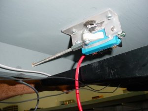
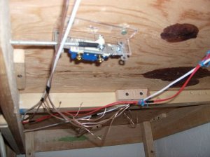
I took an eyelet and epoxied it into a 10-24 rod coupling. I drilled a hole in the switch handle and then used a screw and nut to attach the eyelet to the handle. A piece of 10-24 all-thread rod screws into the rod coupling and goes out the front of the layout where a drawer knob is glued/threaded on.
The plastic tubing has a circle of plastic glued on as shown. This has a small hole drilled in it to function as a pivot point for the music wire which runs up to the switch. A small hole is drilled in the electrical switch handle and the music wire is epoxied into that.
The plastic tubing has a circle of plastic glued on as shown. This has a small hole drilled in it to function as a pivot point for the music wire which runs up to the switch. A small hole is drilled in the electrical switch handle and the music wire is epoxied into that.
N
nachoman
Thanks everyone, I appreciate the responses. ")
I've really enjoyed the thinking and experimenting I've done coming up with this stuff. Now, some of it may be overkill, and I am probably not even saving any money over the commercial stuff, but I have had fun. And there is a certain amount of satisfaction seeing something work that I engineered and built.
I've really enjoyed the thinking and experimenting I've done coming up with this stuff. Now, some of it may be overkill, and I am probably not even saving any money over the commercial stuff, but I have had fun. And there is a certain amount of satisfaction seeing something work that I engineered and built.
Gary, some questions if you don't mind. The plastic piece going up to the switch, does that fit the hole in the table tightly? So far I have not found anything in my area that might work, but if it does not have to be a tight fit, at least I can drill holes and lay track until I find something. And, did you try them without the plastic pieces? I remember seeing photos of electric machines, and they did not have that. And, what if you put a switch at an angle to the table? It looks to me like the mechanism has to have a straight shot to work right. Thanks
Loren
Loren
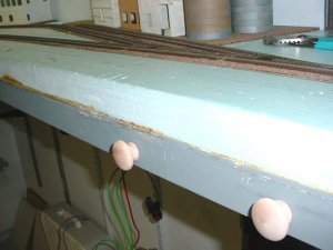
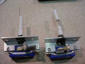
The plastic tube going up through the benchwork is exactly that, some plastic tube bought from the LHS. I don’t remember the exact sizes, but I think it is ½” at the bottom, and then the next two smaller sizes that fit in kind of like a telescoping tube. The two lower tubes are glued together, the upper tube is left so it can slide so fine adjustments for height can be made. The bottom of the tube doesn’t fit tightly in my foam, but the upper part is “snug”. It can be easily moved up and down and twisted to align it, but there is some friction to the fit. If I had it to do over, I might use larger size tubing because I had to file out some grooves in the bottom of the tube and in the aluminum angle iron because of the throw of the wire at the bottom.
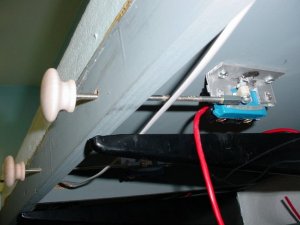
The reason I used the tube is so there would be a pivot point for the steel “music wire” going up to the turn-out. Notice there is a plastic disk with a small hole drilled in it that the wire goes through. Now, actually, after I built some of these, I tried them without the plastic tube and pivot point, and it still worked just fine. You could probably just drill a hole up through the benchwork and not use the tube. But, since I already had some made, I just built them all the same.
One thing the pivot point does is make the pull of the knob direction be the same as the points. If I pull the knob out, the turn-out will be aligned to the front track. If I push it in, it routes to the back track. Without a pivot, it is just the opposite. Still works, but not quite as intuitive.
The tube also has a plastic disk glued on the top, with a slot cut out for the wire to travel back and forth in. Again, not necessary, but this way, the hole in the benchwork is almost completely closed off. Not sure if that is necessary, but I did it. There are some more photos in a thread of mine called "Woohoo finally laying track!".
I have some of the turn-outs at an angle to the edge of the benchwork. The electrical switch itself can be turned a little bit and the rod/knob will still work. And, the wire itself is also free to move a bit out of the exact direction of the electrical switch too. I’m guessing that with my set-up, I could operate a turn-out that was at a 30 degree angle to the edge of the benchwork.
On mine, I have 2” of foam and ¼” of plywood and ¼” roadbed, plus about ½” to the switch handle, so the wire is about 3 inches long. This gives me a lot of play and springiness to work with, things don’t have to be all that exact. If you layout is a lot thinner, then you will have to do some experimenting and testing. With a short length of wire, things could be very different, and require tighter tolerances of construction. The electrical switches have quite a large throw from front to back versus what is actually needed at the turn-out. The amount the wire moves can be adjusted by drilling the hole in the switch handle closer to the pivot point of the electrical switch.
If any of this is confusing, just keep asking questions. I’ll give you all the help I can, will take more pics, whatever you need, I’ll even see what I can design for a thinner benchwork if you need me too. How thick is your benchwork BTW? And, if you decide to go another route, that won’t hurt my feelings either.
Thanks for replying Gary. I have found everything I need except the plastic tubes. I was looking everywhere except the lhs for those.ops: I was going to try tonight without the tubes and see what happens. If that did not work, I was going to try wire nuts for the tubes. I will let you know how it goes.
Loren
ops: I was going to try tonight without the tubes and see what happens. If that did not work, I was going to try wire nuts for the tubes. I will let you know how it goes.Loren
Gary, I cobbled one together tonight, mounted it to a test board with a snap switch, and it works GREAT ! Didn't even need the tube, works great without it.
Thanks for the great idea and the great help.
Loren
Thanks for the great idea and the great help.
Loren
That looks like a great way to power the frog for your intended route too. Neat idea and well thought out. Thanks for sharing.
Greg
Greg
grewsome said:Gary, I cobbled one together tonight, mounted it to a test board with a snap switch, and it works GREAT ! Didn't even need the tube, works great without it.
Thanks for the great idea and the great help.
Excellent! Looking forward to some photos.
Here is a List of Materials. Some experimentation is in order to make these things work with your particular layout thickness.
3-way switch or single pole switch (can be found at any home supply. If you want to feed the frog, or have LEDs for turn-out indicators, you need the 3-way switch. If not, you can get by with a single-pole switch. The 3-ways are quite a bit more expensive than the single-poles.
1” x 1” aluminum angle iron, cut and drilled as shown in photos
10-24 rod coupling
10-24 all-thread rod
Drawer knob
Small eyelet
JB Quik two-part epoxy (fast setting type- used to attach the eyelet to the rod coupling)
8-32 screw and nut
Music wire (steel springy wire – don’t recall the size, just get a size that will fit through the little hole in the turn-out)
#10 wood screws
Various sizes of plastic tube and sheet plastic (you may or may not need this)
After using these for a few days and some mini-ops sessions, I don't think I need any LED indicators on the fascia to indicate turn-out direction. Since this is a shelf layout and not very deep, I can see the turn-outs and the position of the knobs.
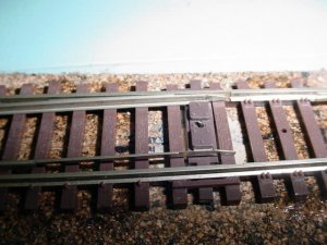
So, looks like I am going to use the switches to power the frogs... one of the reasons is because I am noticing a miniscule power loss on some of the turn-outs when a loco crosses over, maybe a powered frog will help. I wish I would have decided this before I put the track down. Still, it shouldn't be too hard to drill a hole down through the benchwork and attach a wire to the frog.
These are Atlas #4 switches with the metal frog... anyone have any experience with this? Any pointers? Can I use regular solder on the frog or maybe use silver solder? Not sure what kind of metal the frogs are made of.