One of the basics of 'comprehending catenary' is to get an idea of what it looks like, something that just can't be done from simply looking at photos of cars and locos. All that I can get from studying photos whose stars are motive power are ideas concerning details, but not a clear idea of some of the basics. Part of that mystery can be solved by looking at the drawings in this link:
http://img.villagephotos.com/p/2004-7/788680/NHCat1001.jpg
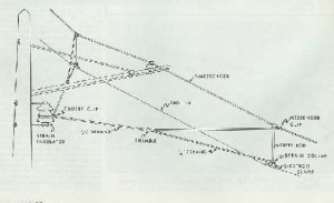
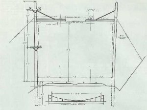
This is a simple diagram of tower and catenary designs used by the NYNH&H RR and the PRR from the 1924 Electric Railway Handbook. In the bottom drawing, you can see how the cross-catenary is used to suspend the catenary with the contact wire. The New Haven RR towers used a suspended I-beam known as a 'flying hanger' to suspend the catenary between towers. For modeling purposes, the PRR catenary profile is the easiest to model with that particular catenary profile available through Model Memories. Also, note the distance between towers...300 feet! That works out to be 3.4 feet between towers on a layout, so there's plenty of space and a layout won't be populated with catenary towers. My goal in modeling catenary isn't to model an exact replica, but to model just enough to provide that level of detail needed for realistic appearance. More to follow!
http://img.villagephotos.com/p/2004-7/788680/NHCat1001.jpg
This is a simple diagram of tower and catenary designs used by the NYNH&H RR and the PRR from the 1924 Electric Railway Handbook. In the bottom drawing, you can see how the cross-catenary is used to suspend the catenary with the contact wire. The New Haven RR towers used a suspended I-beam known as a 'flying hanger' to suspend the catenary between towers. For modeling purposes, the PRR catenary profile is the easiest to model with that particular catenary profile available through Model Memories. Also, note the distance between towers...300 feet! That works out to be 3.4 feet between towers on a layout, so there's plenty of space and a layout won't be populated with catenary towers. My goal in modeling catenary isn't to model an exact replica, but to model just enough to provide that level of detail needed for realistic appearance. More to follow!
") credit to Electric rail review
credit to Electric rail review