Matthysen Junction's coal dumper...

shaygetz

Active Member
May 2, 2003
3,612
0
36
64
www.freewebs.com
webmaster said:
Hmmm... In that case, are the two rods fixed together permanently (rigid)? Obviously the one one the disc rotates, but I must be missing something otherwise the two arms if not fixed rigid will it not just rotate without a lift?

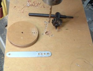
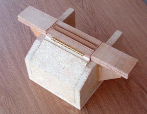
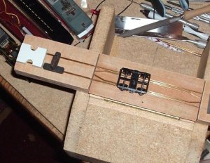
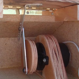
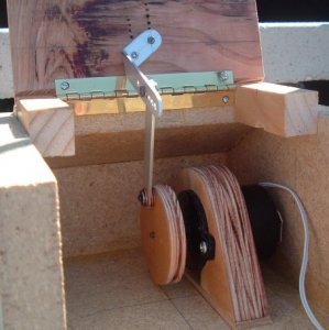
They are not rigid, they pivot at the point where the two connect. Look at the exploded pic of the linkages and you'll see two small brass bearings cut from tubing. They are slightly wider than the thickness of the rods and their washers. When tightened, the fasteners compress on the bearings in a way that keeps the arms free moving without being sloppy. While the bearings are my own design, there is a pic in the article that shows how the arms themselves work but I don't believe I can post that.
 

shaygetz

Active Member
May 2, 2003
3,612
0
36
64
www.freewebs.com
Here's a couple pics showing it in action. In the top view, the bull wheel is turning counter clockwise and the connecting rod has pulled down the lift bar and is now at bottom dead center. In the bottom view, the bull wheel is still turning counter clockwise and the connecting rod, now at top dead center, has pushed the lift bar up and over with the piano hinge guiding the direction of the tilt table.

A close look will show the problem of alignment I am having. As it lifts, the linkage bucks inward because, in this shot, the bull wheel is not far enough forward to prevent this. At bottom dead center the connecting rod should be angled towards the rear at the top, not at the bottom. I may have a horsepower problem as well and will be looking into replacing the motor with one designed to turn the flame element in an electric fireplace as it has a higher HP rating.
 

Attachments

  • robin20.jpg
    robin20.jpg
    47.8 KB · Views: 104
  • robin21.jpg
    robin21.jpg
    49.9 KB · Views: 103

jim currie

Active Member
Jun 29, 2003
1,383
0
36
arizona
Visit site
Bob was looking through a pile of old RR mags today and lo and behold there was a car dumper it is in Bridges and Buildings for model railroads from 1965 the drive mechansism is almost the same as yours the differance being is they used a 12v motor and a gear train if you would like will mail you the page on the car cradle.Yours is looking neater than grits :)
 

shaygetz

Active Member
May 2, 2003
3,612
0
36
64
www.freewebs.com
jim currie said:
Bob was looking through a pile of old RR mags today and lo and behold there was a car dumper it is in Bridges and Buildings for model railroads from 1965 the drive mechansism is almost the same as yours the differance being is they used a 12v motor and a gear train if you would like will mail you the page on the car cradle.Yours is looking neater than grits :)

Thanks guys. Jim, no doubt it's one and the same article I'm working off of. The picture shows an American Flyer S scale 2-8-0 pushing some hoppers into it as one is being dumped into a waiting barge. The gear train in that one is more complex than mine because he cobbled his together from a number of surplus gears. My alignment problem probably comes from the fact that mine is self contained.
 

shaygetz

Active Member
May 2, 2003
3,612
0
36
64
www.freewebs.com
jim currie said:
sign1 it is Bob have you tried moving the top link mount further back ? on looking closer at you pics see you tried that already :)

:rolleyes: sigh...The evidence is that obvious?:rolleyes: I'll figger it out....wall1 wall1 wall1 wall1 wall1 wall1:thumb:
 

webmaster

Member
Feb 17, 2006
155
0
16
54
Surrey, UK
www.budgetwebsiteservices.co.uk
Shaygetz, this is the problem I thought you might have. If the two bars were fixed together strait, with a swivel joint at the top then it would act just like a piston.

See the attached image, sorry it's a bit crude :)

So if you lengthen the bar from the motor and shorten right down the top bar, it should work OK.
 

Attachments

  • tip-table.gif
    tip-table.gif
    5.2 KB · Views: 76

shaygetz

Active Member
May 2, 2003
3,612
0
36
64
www.freewebs.com
Thanks, Jim and Webmaster for your help and extra sets of eyes. In keeping with your advice, what I did today was add three adjustment points to the bull wheel, each an 1/8" apart. Then I drilled the connecting rod with 3 more adjustment points as well, each 3/16" apart. We'll see what that does.

On the other hand, to err on the side of caution, I switched drive motors and mounts. The new motor is a 120 volt beastie used to turn a flame element in an electric fireplace. When I considered the factors involved, a tilt table that weighs about 4 ounces, a hopper car weighted to 5 ounces with a load that'll weigh 4-6 ounces and adding to this the friction of all the linkages---a load that'll push a pound easy---I couldn't go thru all this tinkering only to find the low voltage motor didn't have the ability to keep up with the demand. And I couldn't beat the price...free:thumb: Though a little faster than the other, that and the new mount will enable me to place the motor further in as well, opening up more adjustment possibilities.
 

Attachments

  • robin23.jpg
    robin23.jpg
    49.4 KB · Views: 96
  • robin22.jpg
    robin22.jpg
    61.8 KB · Views: 100

shaygetz

Active Member
May 2, 2003
3,612
0
36
64
www.freewebs.com
So as not to get bogged down on the project, I'm moving on to the rest of it. In an episode of "Tooltime" run amuck, I added "wings" for the approach and departure trackage. Because this is a portable module, I wanted the track to be stable and not prone to missalignment. By making the last 4" in and out solid with the loader itself, I shouldn't have too many alignment issues.

Public Service Announcement---The cigarettes are not mine. Though I've been smoke free for 19 years myself, I allow my assistants and vendors to chuff away in my shop:thumb:
 

Attachments

  • robin24.jpg
    robin24.jpg
    47.2 KB · Views: 99
  • robin25.jpg
    robin25.jpg
    63.6 KB · Views: 97

shaygetz

Active Member
May 2, 2003
3,612
0
36
64
www.freewebs.com
The approach and departure track are in. I snag track gauges at every opportunity, often found at the bottom of parts specials picked up at swap meets...just can't have too many of them. Shown is a 40' quad hopper, the longest the dumper can take. I deviated from the plans by adding 7 scale feet to the length of the tilt table so that it could handle them.

Kadee uncoupling magnets are placed at each end of the tilt table to facilitate the push on/drift off operation of the dumper. Cars will be pushed up slowly from one side, dumped, pushed off of the table, then allowed to drift down to a waiting staging track thru a "boomerang" track. Cars drift down thru a spring switch, then up a short stretch of track. They then run down thru the already thrown spring switch and roll into a waiting string of empties at the bottom of the run.
 

Attachments

  • robin26.jpg
    robin26.jpg
    56.7 KB · Views: 95
  • robin27.jpg
    robin27.jpg
    49.4 KB · Views: 97
  • robin28.jpg
    robin28.jpg
    45.5 KB · Views: 95

webmaster

Member
Feb 17, 2006
155
0
16
54
Surrey, UK
www.budgetwebsiteservices.co.uk
Hehe, I love to tinker with small engineering projects like the one your doing.:D

You could always try a variable resistor in-line with the + on the power to slow the motor slightly?? Also, how are you going to hold the cars on the track? are you going to make some sort of cage?
 

shaygetz

Active Member
May 2, 2003
3,612
0
36
64
www.freewebs.com
webmaster said:
Hehe, I love to tinker with small engineering projects like the one your doing.:D

You could always try a variable resistor in-line with the + on the power to slow the motor slightly?? Also, how are you going to hold the cars on the track? are you going to make some sort of cage?

That's probably why I tend to think of myself as a model train enthusiast vs. a model railroader, I simply like to tinker with the little boogers without a sense or desire to put them together into a cohesive overall "railroad". This dumper will operate but there will be no Point A to recieve coal from or Point B to ship coal to, it'll just be a cool working model of an old tilt dumper that will be in my layout. If anything, it gives an operational goal now that all my hoppers have to meet, i.e. working couplers, proper weight, free rolling wheelsets, etc.

As for the variable resistor, while I've built my own transistor throttle and DCC decoder test station and can read schematics, I couldn't tell you a thing about how to use them or any other device like them. I do know that the motors do not run off of light dimmer switches to slow down the speed if that helps with any controller ideas.

The cars will be in a cage that holds them to the rails. Unlike the prototype, which holds the cars via two large clamp devices on either end of the car, the cage will have slide rails that guide and slightly press down on either side of the car's top edges. Needless to say, this device limits you to one or two brands of hopper as the slide rails have to be made to close tolerances and are rather unforgiving of variety. Fortunately, I'm an Athearn fan and the thought of having a reason to own a whole string of their 34 footers just makes me feel all warm and fuzzy.:thumb:
 

shaygetz

Active Member
May 2, 2003
3,612
0
36
64
www.freewebs.com
Ralph said:
Bob this is just getting cooler and cooler! Thanks for the step by step in craftmanship, creativity, and problem solving!
Ralph

Thanks, Ralph, moving on to the superstructure, the chute, cable tower control room and such is just around the corner. I intend to push on with it as I can fiddle with the mechanism while the rest is going together.

On an interesting note, I have seen this in a recent MR, the past 2-3 years anyway, where a modeler had this on his layout, it was even captioned as such and it was pointed out that it had indeed come from the book I have. I shoulda maybe took the hint or saw the omen as his was manually operated:rolleyes: :thumb:
 

jim currie

Active Member
Jun 29, 2003
1,383
0
36
arizona
Visit site
As for the variable resistor, while I've built my own transistor throttle and DCC decoder test station and can read schematics, I couldn't tell you a thing about how to use them or any other device like them. I do know that the motors do not run off of light dimmer switches to slow down the speed if that helps with any controller ideas.

Bob all a variable risistor is a sewing machine foot pedal.
 

shaygetz

Active Member
May 2, 2003
3,612
0
36
64
www.freewebs.com
jim currie said:
Bob all a variable risistor is a sewing machine foot pedal.

I'll check out the local thift stores and see if I can't bag one there. If nothing else, I can use it on my Dremel. Thanks, Jim.:thumb: