

http://www.alkrug.vcn.com/rrfacts/hp_te.htm A discussion of issues of pulling ability on real railroads.
Locomotive weight standards?
- Thread starter Gary S.
- Start date
You are using an out of date browser. It may not display this or other websites correctly.
You should upgrade or use an alternative browser.
You should upgrade or use an alternative browser.
Thanks for that link, Triplex. A clear explanation in easy-to-understand terms. I've added it to my favourites. :thumb:
Wayne
Wayne
With HO scale length dimensions being 1/87th of the prototype, what about scale weight? I am thinking that weight would be related to volume instead of just length, so to convert the weight of the real thing to weight of the model, we would divide by 87 cubed.*
A typical GP40 weights 280,000 pounds according to the article. If we divide by 87 cubed, then a HO scale GP40 should weigh 6.8 ounces. But they actually weigh 2 or 3 times that!!! Talk about out of scale! So much for the so-called pRoTotyPiCaL modeling and rivet counters
*pure speculation on my part
Supposedly, weight can't be "scaled down", but the rolling resistance of the first train cited works out to 1% (of train weight) per percent of grade. Which explains why my small steamers can prevent a 100 ounce train from rolling down a 2.5% grade, even though they can't actually move the train. Now if I can calculate how he got the figure for rolling resistance through a curve, it should be possible to engineer a model locomotive to suit a specific requirement. After all, NorthWest Short Line does give horsepower ratings for all the motors that they sell!
Wayne
Wayne
Isn't a Bowser boiler die cast and pretty heavy as it stands? If you have voids or steam and sand domes that are empty, you could fill them with epoxy and lead bird shot. Bowser also has painted engineer and firemen figure made from brass castings. Those should add some weight to the cab.
I have a couple of Bowser (ex-Varney) boilers that I'm using to modernise a pair of Bachmann 10 Wheelers. While they are cast metal, I've cast new lead boiler weights for them and will also be using lead-filled brass tubing for the air tanks. With a metal boiler, you could even cast extra weight directly in the cavities inside the casting, instead of making moulds.
Wayne
Wayne
Leon, I use .015" sheet aluminum, although scrap aluminum siding will also work - if you use the siding material, the painted side goes to the outside of the mould. The moulds all have an open top, so for square or rectangular weights, you need to decide which side will be open - the opposite side will be the bottom (you can install these weights with any side as the bottom, but because the molten lead forms a convex meniscus, the top of the weight, when it's poured, will be somewhat irregular.) You can file these weights to make all sides flat, if needed (exercise the usual precautions when handling lead), but for car weights, etc., the convex surface usually causes no problems.
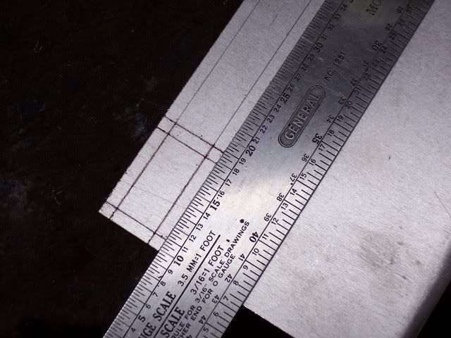
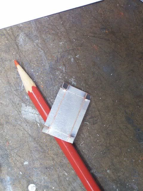
To make the mould, for example, for a 1"x2"x 1/4" weight, you'll need a piece of aluminum 1 1/2"x2 1/2". Measure 1/4" in from each edge, then use a utility knife and straightedge to scribe along these lines, from edge to edge, with the lines crossing near the corners of the sheet - two or three passes on each should do, depending on the pressure applied to the knife. Using tinsnips, cut along the 1/4" line at each corner from one edge only - in other words, cut all of the 1/4" long lines extending from either the long edges or the short edges. End the cuts just short of the point where the lines intersect. Now, using pliers or a hammer and a straightedge, fold the main part of the sides that you cut so that they're at right angles to the bottom of the mould. Next, using pliers, fold the remaining sides in a similar manner - the 1/4" protruding "tabs" are then wrapped around the intersecting sides, effectively closing the sides of the mould. Straighten the bottom and sides of the mould as required, using pliers, then place it, open side up, on a metal surface, and pour the molten lead.
Here is a mould being constructed for a simple weight. Since a scale rule is always at hand, I'm making the mould using HO scale measurements of 3'6"x7'0"x1' high
Laying out the folding pattern:
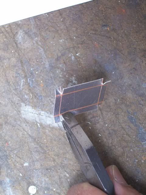
Rather than cut the pattern from the sheet using tinsnips, I simply score a couple more passes with the knife, then bend the sheet by hand - a couple of bends back-and-forth, and the mould blank will break free:
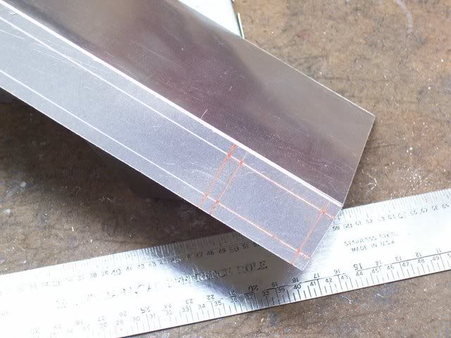
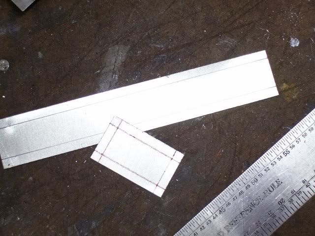
Use the snips to make the short cuts as shown - I like to make them two per side, on sides opposite one another, as shown. This makes it easier to spread the mould sides slightly when attempting to remove the freshly cast weight:
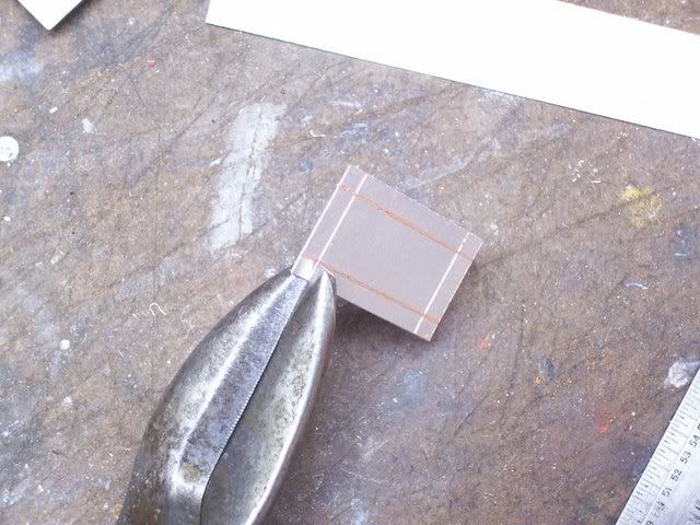
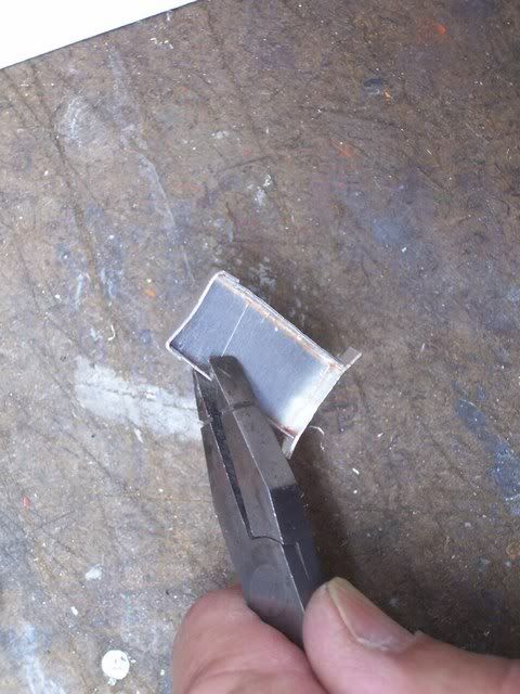
Here I'm using pliers to bend the sides of the mould into position. The score line can be on either the inside or outside of the mould; it doesn't seem to make a difference:
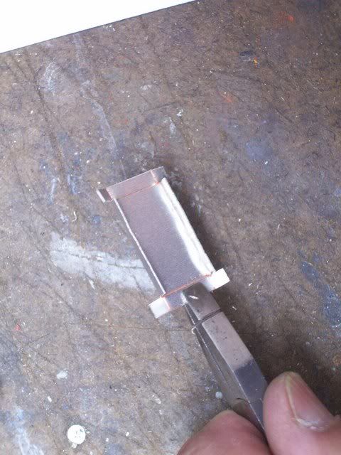
The protruding "tabs" are bent around the adjoining sides, as shown, then the pliers are used to straighten the mould as necessary:
I make moulds to suit what I need, including a complete set, left and right, to add weights to the underframe of a Walthers GSC flatcar. Here are a few different moulds:
These two sizes are the ones which I use the most. The small one is, in HO scale, 3'6"x7'x1'6" high, and the large one is 7'x7'x1'6"high. Shown with each is a representative lead weight. Depending on how much the mould is filled, the thickness (and weight) can vary. These were filled to the top of the mould, plus a bit extra (the surface tension of the molten lead allows it to "pile-up" higher than the sides of the mould). The smaller of the two is one ounce, approximately, while the bigger one is two ounces.
For a cylindrical weight, I cut a piece of aluminum to the length required, then form it around an object similar in diameter to what's required - it doesn't need to be the exact same diameter. The curved sheet should overlap itself by at least 1/2". Using calipers or a ruler, adjust the diameter by loosening or tightening the "tube", then use some soft wire to form a couple of retaining bands, as shown in the photo.
The weights being made in the above photo have a step in the shape, with only part of the lead forming a full cylinder, hence the oddly-shaped insert. For most full cylinder shapes, you can pour the lead without bothering to make a bottom for the mould - working on a metal surface, simply use channel-locks or slip-jointed pliers to hold the mould upright and in full contact with the metal surface while you pour the lead. The cold surface of the metal will cause the molten lead to solidify almost on contact, preventing leakage.
You can also use pieces of metal pipe as moulds, even leaving the mould in place when the weight is used - the weights shown at the left of the above photo were made in copper water pipe - two are still in the capped pipe, while the other two have had the pipe removed. Usually, the pipe has to be cut away to release the lead weight, and even the sheet aluminum moulds for cylindrical weights are usually good for only one use. The rectangular moulds, however, can be used several times, although the repeated partial spreading and re-closing of the sides to "get the lead out" will eventually fatigue the metal until it breaks.
I hope that this little demonstration will prove to be of use.
Wayne
To make the mould, for example, for a 1"x2"x 1/4" weight, you'll need a piece of aluminum 1 1/2"x2 1/2". Measure 1/4" in from each edge, then use a utility knife and straightedge to scribe along these lines, from edge to edge, with the lines crossing near the corners of the sheet - two or three passes on each should do, depending on the pressure applied to the knife. Using tinsnips, cut along the 1/4" line at each corner from one edge only - in other words, cut all of the 1/4" long lines extending from either the long edges or the short edges. End the cuts just short of the point where the lines intersect. Now, using pliers or a hammer and a straightedge, fold the main part of the sides that you cut so that they're at right angles to the bottom of the mould. Next, using pliers, fold the remaining sides in a similar manner - the 1/4" protruding "tabs" are then wrapped around the intersecting sides, effectively closing the sides of the mould. Straighten the bottom and sides of the mould as required, using pliers, then place it, open side up, on a metal surface, and pour the molten lead.
Here is a mould being constructed for a simple weight. Since a scale rule is always at hand, I'm making the mould using HO scale measurements of 3'6"x7'0"x1' high
Laying out the folding pattern:
Rather than cut the pattern from the sheet using tinsnips, I simply score a couple more passes with the knife, then bend the sheet by hand - a couple of bends back-and-forth, and the mould blank will break free:
Use the snips to make the short cuts as shown - I like to make them two per side, on sides opposite one another, as shown. This makes it easier to spread the mould sides slightly when attempting to remove the freshly cast weight:
Here I'm using pliers to bend the sides of the mould into position. The score line can be on either the inside or outside of the mould; it doesn't seem to make a difference:
The protruding "tabs" are bent around the adjoining sides, as shown, then the pliers are used to straighten the mould as necessary:
I make moulds to suit what I need, including a complete set, left and right, to add weights to the underframe of a Walthers GSC flatcar. Here are a few different moulds:
These two sizes are the ones which I use the most. The small one is, in HO scale, 3'6"x7'x1'6" high, and the large one is 7'x7'x1'6"high. Shown with each is a representative lead weight. Depending on how much the mould is filled, the thickness (and weight) can vary. These were filled to the top of the mould, plus a bit extra (the surface tension of the molten lead allows it to "pile-up" higher than the sides of the mould). The smaller of the two is one ounce, approximately, while the bigger one is two ounces.
For a cylindrical weight, I cut a piece of aluminum to the length required, then form it around an object similar in diameter to what's required - it doesn't need to be the exact same diameter. The curved sheet should overlap itself by at least 1/2". Using calipers or a ruler, adjust the diameter by loosening or tightening the "tube", then use some soft wire to form a couple of retaining bands, as shown in the photo.
The weights being made in the above photo have a step in the shape, with only part of the lead forming a full cylinder, hence the oddly-shaped insert. For most full cylinder shapes, you can pour the lead without bothering to make a bottom for the mould - working on a metal surface, simply use channel-locks or slip-jointed pliers to hold the mould upright and in full contact with the metal surface while you pour the lead. The cold surface of the metal will cause the molten lead to solidify almost on contact, preventing leakage.
You can also use pieces of metal pipe as moulds, even leaving the mould in place when the weight is used - the weights shown at the left of the above photo were made in copper water pipe - two are still in the capped pipe, while the other two have had the pipe removed. Usually, the pipe has to be cut away to release the lead weight, and even the sheet aluminum moulds for cylindrical weights are usually good for only one use. The rectangular moulds, however, can be used several times, although the repeated partial spreading and re-closing of the sides to "get the lead out" will eventually fatigue the metal until it breaks.
I hope that this little demonstration will prove to be of use.
Wayne
Wayne, I just knew you'd have some high tech, Norm Abrams crafted, slick way to weigh out rolling stock that would shame us fishing weight and buckshot guys into the corner:thumb::thumb::thumb:...I'm assuming the "convex meniscus" is similar to that point of the pile where the buckshot starts rolling away from the car being weighted? :mrgreen:
Yeah, it's pretty much the same. It's easy enough to over-fill the moulds, too, but playing the flame of the torch over the spill will cause some of it to flow back to the mould and the rest to separate. Once it cools, it goes back in the pot for re-melting. :-D:-D
By the way, sorry about the over-size pictures - they're from photobucket, and I didn't realise that they'd post so large.ops:
Wayne
It's easy enough to over-fill the moulds, too, but playing the flame of the torch over the spill will cause some of it to flow back to the mould and the rest to separate. Once it cools, it goes back in the pot for re-melting. :-D:-DBy the way, sorry about the over-size pictures - they're from photobucket, and I didn't realise that they'd post so large.
ops:Wayne
Well Wayne; you did it again. Many thanks for all the info and photo's for making lead weights. As always--you really come through. Thanks again.
cidchase
Active Member
It seems as though there is no thought that the extra weight will increase the axle loading, the wear on axle bearing surfaces, the torque on the notoriously weak :curse: axle gears, and the current draw through the motor and commutator.
Everything will wear out eventually. I think adding too much weight may hasten a trip to the roundhouse! Maybe, as long as it will still slip, it's OK, but maybe that is not the only consideration!!
Just my er fen. :mrgreen:
Everything will wear out eventually. I think adding too much weight may hasten a trip to the roundhouse!
Maybe, as long as it will still slip, it's OK, but maybe that is not the only consideration!!Just my er fen. :mrgreen:
Well, I doubt that the relatively minuscule amount of weight that one could fit into most models will prematurely wear-out the wheel bearings, although it stands to reason that they will wear faster. I doubt that I'd live long enough to see an axle failure from a hotbox, though, even with very heavy useage. :-D:-D As for axle loadings, I find that the practice of adding weight to both cars and locos encourages us to build properly engineered bridges, in strict adherence to the required Cooper ratings. :-D
If there are weak axle gears in the equation, better to find the problem and fix it - the four Athearn Mikados which I modified with extra weight, as shown HERE are locos which were noted for premature gear failure, yet none of mine have yet experienced it. Their regular service on my layout is pulling 100 ounce coal trains.
As for current draw, it will climb as long as the train is moving and there's weight being added to the drawbar. Once the wheels begin to slip, the current will draw will drop to what it would be for a no-load situation. As a test, I added a 20 oz. lead "saddle" atop the boiler of one of those Athearn Mikes, and with the tender manually restrained, the loco easily slipped its wheels. Other than full-body cab units, most model locos don't have enough room in their body shells to hide enough weight to do any damage to the motor or drive train. (That's assuming the motor is of reasonable quality and likewise for the drivetrain.)
Just as important as adding extra weight for added tractive effort is making sure that the weight is "balanced". With diesels, this is both easier and less crucial than with steam locos. For steamers, the loco (sans tender) should balance about the centre point of its driver wheelbase. A Pacific or Hudson should balance at the contact point of the second driver set, while a Mikado, Mountain, Northern, or 0-8-0 should balance mid-way between the second and third driver sets. The balance test should be conducted with all lead and/or trailing trucks in place, as the springing on these can shift the balance point. A balanced loco, at its "stock" weight, is likely to pull better than the same loco with an extra 4 oz. of lead in its cab, while a similar loco with the extra 4 oz. balanced around the driver wheelbase will out-pull both.
Wayne
:-D:-D As for axle loadings, I find that the practice of adding weight to both cars and locos encourages us to build properly engineered bridges, in strict adherence to the required Cooper ratings. :-DIf there are weak axle gears in the equation, better to find the problem and fix it - the four Athearn Mikados which I modified with extra weight, as shown HERE are locos which were noted for premature gear failure, yet none of mine have yet experienced it. Their regular service on my layout is pulling 100 ounce coal trains.
As for current draw, it will climb as long as the train is moving and there's weight being added to the drawbar. Once the wheels begin to slip, the current will draw will drop to what it would be for a no-load situation. As a test, I added a 20 oz. lead "saddle" atop the boiler of one of those Athearn Mikes, and with the tender manually restrained, the loco easily slipped its wheels. Other than full-body cab units, most model locos don't have enough room in their body shells to hide enough weight to do any damage to the motor or drive train. (That's assuming the motor is of reasonable quality and likewise for the drivetrain.)
Just as important as adding extra weight for added tractive effort is making sure that the weight is "balanced". With diesels, this is both easier and less crucial than with steam locos. For steamers, the loco (sans tender) should balance about the centre point of its driver wheelbase. A Pacific or Hudson should balance at the contact point of the second driver set, while a Mikado, Mountain, Northern, or 0-8-0 should balance mid-way between the second and third driver sets. The balance test should be conducted with all lead and/or trailing trucks in place, as the springing on these can shift the balance point. A balanced loco, at its "stock" weight, is likely to pull better than the same loco with an extra 4 oz. of lead in its cab, while a similar loco with the extra 4 oz. balanced around the driver wheelbase will out-pull both.
Wayne