Location of plastic rail joiners OK ?

Biased turkey

Active Member
Apr 10, 2006
912
0
36
75
Montreal, Canada Eh
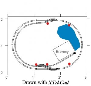
The "main line is the oval"
I insulated 1 section on the right part of the oval ( next to the pond so the train on the main line is stopped there while the switcher can do some run around on the left side of the layout
I insulated the run around track so the switcher can wait there with a few boxcars while the complete main oval will be powered.
Of course the spur is insulated too, so the switcher and 1 boxcar can wait there
Does it mak any sense ?

TIA for any suggestion and/or improvment.
 

Attachments

  • PlasticJoiner.jpg
    PlasticJoiner.jpg
    41.6 KB · Views: 161

60103

Pooh Bah
Mar 25, 2002
4,754
0
36
Brampton, Ontario, Canada
Visit site
Not quite how I'd do it, but it will work.
Consider this: put the insulated joiners at the frog end of the switches. You now have the blocks: 1) by the pond including both switches 2) outer loop left side 3) inner loop (siding) 4) the brewery spur.
Now you can park a train on the outer loop and run the other one all the way around using the passing siding
or park one in the passing siding and use the loop
or park one in the spur and use either route.
 

pgandw

Active Member
Jul 9, 2005
1,002
0
36
60103 said:
Not quite how I'd do it, but it will work.
Consider this: put the insulated joiners at the frog end of the switches. You now have the blocks: 1) by the pond including both switches 2) outer loop left side 3) inner loop (siding) 4) the brewery spur.
Now you can park a train on the outer loop and run the other one all the way around using the passing siding
or park one in the passing siding and use the loop
or park one in the spur and use either route.

I concur with the above. If you want the abiltiy to run two short trains chasing each other around the loop, you will have to break the pond side, the left side, and the passing track blocks each into 2 separate blocks. Given the small size of the layout, though, I wouldn't bother with this capability.

See my rules on creating DC blocks at http://www.the-gauge.com/showthread.php?t=26709 for more details.

yours in DC wiring
 

Biased turkey

Active Member
Apr 10, 2006
912
0
36
75
Montreal, Canada Eh
The track plan looks small, I posted it in the gallery, maybe it'll have a bigger size.
Forget about it, the size is the same because that's the size Xtrkcad save it as a .bmp file.
Sorry,

img%5D


img%5D
 

pgandw

Active Member
Jul 9, 2005
1,002
0
36
Biased turkey said:
pgandw, do you mean like that ?

Exactly. I can't tell whether you are insulating one rail or both rails.

Insulating one rail is called common rail, and can reduce wiring somewhat. But you must be consistent which rail you insulate throughout the layout. Common rail has become less used recently because it is not compatible with DCC.

You may need some additional gaps or insulated rail joiners depending on turnouts used. Atlas turnouts do not need any additional gaps or insulated rail joiners.

yours in DC wiring
 

Biased turkey

Active Member
Apr 10, 2006
912
0
36
75
Montreal, Canada Eh
I put the red dot in the middle of the track for clarity's sake ( at least I thought lol ) but of course in reality I'll insulate 1 rail, the way I did it on the original schematic.
 

pgandw

Active Member
Jul 9, 2005
1,002
0
36
Biased turkey said:
Thanks for your feedback people.
I forgot to mention that I'll only run 1 train at a time.

If you never intend to have more than 1 engine on the layout at a time, you don't need any gaps or insulated joiners (assuming Atlas or similarly wired turnouts).

The blocks are only needed to prevent 2 locomotives being controlled by one throttle at the same time. So, if a second loco is on the layout, even if standing still while the other is running, the blocks are needed.

Hope this helps and makes sense.
 

Biased turkey

Active Member
Apr 10, 2006
912
0
36
75
Montreal, Canada Eh
60103 said:
Not quite how I'd do it, but it will work.
Consider this: put the insulated joiners at the frog end of the switches. You now have the blocks: 1) by the pond including both switches 2) outer loop left side 3) inner loop (siding) 4) the brewery spur.
Now you can park a train on the outer loop and run the other one all the way around using the passing siding
or park one in the passing siding and use the loop
or park one in the spur and use either route.

But if I do it that way, my switcher won't have any place to do some runaround. If I do it the way showned in the 1st schematic ( with only a 4 tracks block along the pond ) my MP15DC switcher has 1 section to clear the switch and do some run around on the left inside and outside curves while the main train ( GP9 ) is "far away " standing on the block along the pond.