

I've wired up my relays but i haven't powered them yet. I'm using 2 toy transformers under the table could i use those power xformers w/ the dial set to only give out 3volts dc to my led's negating the need for a resistor? Or do i HAVE to have a resitor inline no matter what my input voltage to the led's are?
Led voltage question
- Thread starter YmeBP
- Start date
You are using an out of date browser. It may not display this or other websites correctly.
You should upgrade or use an alternative browser.
You should upgrade or use an alternative browser.
Urgent, Urgent.
Before screwing anything up, a diode always requires an inline resistor.
I'll post later about the resistor value that would put you in the ballpark.
Any idea about who's the manufacturer and what part # it is ?
Before screwing anything up, a diode always requires an inline resistor.
I'll post later about the resistor value that would put you in the ballpark.
Any idea about who's the manufacturer and what part # it is ?
Yes, there's no easy way to assure that you're going to get 3 VDC out of your power pack. For the most part, it probably isn't regulated, and even then, if you push the lever just a tad too high you're going to blow your LED.rogerw said:Is that for current limiting?
Exactly. Even if the transformer puts out exactly the voltage you expect, the currect is uncontrolled, except by the good graces of the LED. With the resistor you can control the current to the LED, and run it a less that it's maximum. It really is necessary.rogerw said:Is that for current limiting?
Jeff
YmeBP - a simple way of getting approximately 3 volts from that toy transformer would be to put a 3.0 volt Zener diode across the output of the transfomer, with a resistor inline with this diode.. You will have a very close voltage to that of what you are looking for across the Zener diode. The resistor values will have to be determined with this formula:
Zener diodes are widely used to regulate the voltage across a circuit. When connected in parallel with a variable voltage source so that it is reverse biased, a zener diode conducts when the voltage reaches the diode's reverse breakdown voltage. From that point it keeps the voltage at that value.
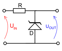
In the circuit shown, resistor R provides the voltage drop between UIN and UOUT. The value of R must satisfy two conditions:
These devices are also encountered, typically in series with a base/emitter junction, in transistor stages where selective choice of a device centred around the avalanche\zener point can be used to introduce compensating temperature co-efficient balancing of the transistor PN junction. An example of this kind of use would be a d.c. error amplifier used in a stabilized power supply circuit feedback loop system.
I know a lil far fetched in understanding this explanation, but in electrical terms its what you are looking for..
Zener diodes are widely used to regulate the voltage across a circuit. When connected in parallel with a variable voltage source so that it is reverse biased, a zener diode conducts when the voltage reaches the diode's reverse breakdown voltage. From that point it keeps the voltage at that value.

In the circuit shown, resistor R provides the voltage drop between UIN and UOUT. The value of R must satisfy two conditions:
- R must be small enough that the current through D keeps D in reverse breakdown. The value of this current is given in the data sheet for D. For example, the common BZX79C5V6[1] device, a 5.6 V 0.5 W zener diode, has a recommended reverse current of 5 mA. If insufficient current flows through D, then UOUT will be unregulated, and less than the nominal breakdown voltage (this differs to voltage regulator tubes where the output voltage will be higher then nominal and could rise as high as UIN). When calculating R, allowance must be made for any current flowing through the external load, not shown in this diagram, connected across UOUT.
- R must be large enough that the current through D does not destroy the device. If the current through D is ID, its breakdown voltage VB and its maximum power dissipation PMAX, then IDVB < PMAX.
These devices are also encountered, typically in series with a base/emitter junction, in transistor stages where selective choice of a device centred around the avalanche\zener point can be used to introduce compensating temperature co-efficient balancing of the transistor PN junction. An example of this kind of use would be a d.c. error amplifier used in a stabilized power supply circuit feedback loop system.
I know a lil far fetched in understanding this explanation, but in electrical terms its what you are looking for..
I'm no wizz kid with LEDS, but don't they have to be wired with the correct polarity to the "legs". If wiring to a toy transformer wouldn't there also be the danger of flipping the direction switch (inadvertently) on the transformer and blowing the LEDS to a parallel universe..??
I've asked that question before toosteamhead said:I'm no wizz kid with LEDS, but don't they have to be wired with the correct polarity to the "legs". If wiring to a toy transformer wouldn't there also be the danger of flipping the direction switch (inadvertently) on the transformer and blowing the LEDS to a parallel universe..??
") in another thread..
in another thread..To make things as simple as string theory, what about bi color led's w/ only 2 legs? How would that fit into the diagram?
I have wires run for leds but i think i'm going to hold off until i can crack my brain open and make this sink in
. For whatever reason i just don't get it hhahaha.String theory is a snap compared to this...Wouldn't you be better off using a small power pack (the Wal-Mart variety) with a fixed voltage output (and fixed polarity)..?? If possible with a low voltage output...
YmeBP said:I've asked that question before too
To make things as simple as string theory, what about bi color led's w/ only 2 legs? How would that fit into the diagram?
I have wires run for leds but i think i'm going to hold off until i can crack my brain open and make this sink in
I'll try to answer. The answer is yes and no. The LED can handle a reverse voltage, probably at least 5 volts, so you are probably safe there. But you are correct that they don't really like a reverse voltage.
As far as the bicolor, 2 legged LEDs, they light one color with the voltage one way, and the other color with the voltage the other. It's pretty much thwo LEDs pointed opposite directions, the current flows through one or the other, and still needs to be controlled with a resistor.
Here's the quick summary of LEDs. In the forward (lighted) direction they are going to drop a fix (or nearly so) voltage, in the neighborhood of 2 volts (but depends on the color). They also are rated for a maximum current (manys time around 30 mA). In this case it would be fine as a light with 20 mA, and last longer. So the resistor serves two functions. It drops any excess voltage, and it limits the current. So, to figure what resistor you need, take the supply voltage and subtract the LED drop. Then divide that voltage by the current you want. For this example, 12V-2V=10V. 10V/20mA=500 Ohms.
Here's a calculator that does the work. They are conservative on the power rating of the resistor, and they round the resistance to values you can actually buy.
http://led.linear1.org/1led.wiz
Jeff
steamhead said:String theory is a snap compared to this...Wouldn't you be better off using a small power pack (the Wal-Mart variety) with a fixed voltage output (and fixed polarity)..?? If possible with a low voltage output...
That will work, but you still need the resistor. And you want to make sure it can provide the current you need. For example, a 500mA transformer would 'only' drive around 25 LEDs in the example above.
Jeff
You need a current source. Preferably a nice stable DC supply. 12 volts DC is fine. You need a current limitiing resistor in series with the LED. Most LEDs will look fine indoors with 10 to 20 milliamps of current, but it is a good idea to check the device's rating if you have a spec sheet for it. If you have a 12 VDC supply, try a 680 ohm, 1/4 watt resistor.
Hooking up a LED backwards will result in zero current flow and zero damage. It just won't light. LED stands for light emitting diode, and a diode is a device that allows current to flow in one direction but not the other. To "blow" the LED that way would require some really high reverse voltage. 12 volts isn't going to do it, unless you are working with something out of the ordinary.
The 3 volt regulator show earlier in the thread is an unneeded complication, in my opinion. You would still need a series current limiting resistor, but it would have to be a critical small value that might be hard to obtain. You aren't gaining anything other than complexity and yet another circuit to troubleshoot when nothing works right.
O.k. sounds like i shouldn't use my toy transformers to power my led's unless i can filter them and regulate the output.. and for all that trouble (caps and the likes) i might as well buy a regulated dc power supply. I do have other dc transformers laying about i have to look and see what voltage and amperage they are. So if i get a regulated dc powersupply ( probably have 6v and 12v) i still need a resistor.
Now i have miniatronics led's w/ resistors. I guess it wouldn't hurt to just wire up one and see what happens :0 heheh.
So ... if you check this thread, http://www.the-gauge.com/newreply.php?do=newreply&noquote=1&p=267602, i've finished the layout and actually running engines it's fun i never thought it would be so much fun running on a 4x8 . I do however have to get teh leds to work as i can't figure out what polarity etc my blocks are and what direction my turnouts are pointed .
Now i have miniatronics led's w/ resistors. I guess it wouldn't hurt to just wire up one and see what happens :0 heheh.
So ... if you check this thread, http://www.the-gauge.com/newreply.php?do=newreply&noquote=1&p=267602, i've finished the layout and actually running engines
it's fun i never thought it would be so much fun running on a 4x8 . I do however have to get teh leds to work as i can't figure out what polarity etc my blocks are and what direction my turnouts are pointed .YmeBP said:O.k. sounds like i shouldn't use my toy transformers to power my led's unless i can filter them and regulate the output.. and for all that trouble (caps and the likes) i might as well buy a regulated dc power supply. I do have other dc transformers laying about i have to look and see what voltage and amperage they are. So if i get a regulated dc powersupply ( probably have 6v and 12v) i still need a resistor.
Now i have miniatronics led's w/ resistors. I guess it wouldn't hurt to just wire up one and see what happens :0 heheh.
So ... if you check this thread, http://www.the-gauge.com/newreply.php?do=newreply&noquote=1&p=267602, i've finished the layout and actually running engines
I don't really think there is any reason not to use the supplies you have, as long as it's DC. The easiest thing to do would be do set them to max, and measure the voltage. Tape up the reverse switch, and plug them in to a power stip you can switch off. Then calculate the resistor(s) you need, wire it up, and call it done. The output certainly doesn't need to be filtered and regulated. You can even use AC, so long as it's not too big. The LEDs would only light half the time, but you'd see them fine.
Jeff
You didn't mention it, but are you using DCC, or plain ol' analog DC..?? If you're on DC, I used a very simple system to achieve what you are attempting to do...I used little 12 V."Microlamps" from R-Shack, and wired these across the insulated gap, wired to one track on the main line, and the opposing track in the insulated section. This way, if the polarity is correct across the insulated gap, the lamp will light. If it doesn't light it means you've got to throw a reversing switch, either on the main line or in the reversing section..Simple.
Jeff is correct. For running lights, even the worse DC supply will do just fine. He's also right about running LED's on AC. An LED is a diode and will only work when current is running in the forward direction so it will "flicker" at a 60 times a second rate and you won't notice it. The main thing is to have a current limiting resistor sized for the highest voltage you could get from your supply so that there'll be no accidental overvoltage surprises. Even if you were able to regulate the voltage down to 3 volts, it wouldn't be a good idea to go without some current limiting otherwise it wouldn't take much of a voltage change to cause problems.
The layout i'm working on now is dc to start until my kids can get the hand of it then i'll switch them to dcc.steamhead said:You didn't mention it, but are you using DCC, or plain ol' analog DC..?? If you're on DC, I used a very simple system to achieve what you are attempting to do...I used little 12 V."Microlamps" from R-Shack, and wired these across the insulated gap, wired to one track on the main line, and the opposing track in the insulated section. This way, if the polarity is correct across the insulated gap, the lamp will light. If it doesn't light it means you've got to throw a reversing switch, either on the main line or in the reversing section..Simple.
That is a great idea
i have some GOW 12v lights i can use too thanks!!!