Le Courbet French battle cruiser from Modelik

MikeBer

Active Member
Feb 26, 2008
102
216
46
Port Ellizabeth South Africa
:welcome1:
I am a newbie to card modelling. I normally model wooden ships (Titanic & Bismarck partworks and Danmark & Victory kits). I will be starting the build on the COURBET hopefully this week. This is the ship that my father came over to England on with the free French navy at the beginning of WW11.
 

MikeBer

Active Member
Feb 26, 2008
102
216
46
Port Ellizabeth South Africa
I decided that as far as possible, I would use scanned copies for the construction and keep the originals. Here are some of the hull frame outlines mounted on card prior to cutting out. Due to the method of construction of the hull elements, I decided that it was unnecessary to fix a longitudinal wooden stringer to the keel section to keep it straight down its length.[FONT=&quot]

Hullframework.jpg

[/FONT]
 

MikeBer

Active Member
Feb 26, 2008
102
216
46
Port Ellizabeth South Africa
Laminating frames

Let me start by saying that an Optivisor is a godsend for accurate cutting of the card frames.
Because of the exorbitant cost of spray adhesive, I decided to use a gluestick to stick the scanned copies of the frames to the card. I then roughly cut out the frames (A) and then trimmed them about 5mm oversize all round (B). This enabled the card to be cut much easier as there was less sideways pressure against the craft knife.
I used the craft knife to cut the straight sides (C) using an aluminium straight edge as a guide and the curved sides of the frames (D) were cut freehand, all with the assistance of the optivisor.

Frames1.jpg

Once the framework is complete, I intend spraying it with an aerosol grey primer to seal the card, so another advantage of the glue stick is that the templates can be peeled off the card very easily.

After cutting out the frames, the slots were cut in them (1). Then, the dotted lines were slightly scored and the strip of paper removed (2). The card was then coloured with a highlighter to show the frame position (3) and then the rest of the paper template was removed, not forgetting to transfer the part No’s onto the card (4).

Frames2.jpg
 

jkrenzer

Member
Oct 2, 2007
126
0
16
Syracuse, NY
I have not seen the Courbet form Modelik yet. I did just finish their model of Paris, photos are here on this site. Is the model of Courbet of WWI or WWII?

The Paris also sailed to British ports and Courbet and her were likely very similar in appearance at that time.
 

bclemens

Member
Jan 31, 2008
25
0
16
Springfield, Missouri
Looking forward to this one! MikeBer, thanks for the very clear and detailed account so far. As an ex watchmaker over 50, I can relate to the appreciation of visual augmentation :eek:ops:
Cheers!
Bruce
 

MikeBer

Active Member
Feb 26, 2008
102
216
46
Port Ellizabeth South Africa
Is the model of Courbet of WWI or WWII?

The Paris also sailed to British ports and Courbet and her were likely very similar in appearance at that time.
The Courbet was built in 1910, served in WW1 and was recommisioned for WW11.
My Dad says that he served on the Paris first, attaining his gunnery certificate and he then transferred to the Courbet on which he sailed to Portsmouth with the Free French and joined the British navy. This is the reason that I am building this model.
French battleship Courbet - Wikipedia, the free encyclopedia

Mike
 

MikeBer

Active Member
Feb 26, 2008
102
216
46
Port Ellizabeth South Africa
Lower hull

Tip:- a piece of glass is great when a flat surface is required for gluing the hull elements.

To make it easier to glue the lower hull elements, I cut some tongue depressors into 2mm strips for rib guides.

Strips.jpg


I then cut them to size and glued them onto the lower hull template card.

Glue1.jpg


Glue2.jpg


This will make it easier and simpler to assemble the framework.

Glueframes.jpg


Lowerhull.jpg


Here is the completed lower hull.
 

MikeBer

Active Member
Feb 26, 2008
102
216
46
Port Ellizabeth South Africa
Upper hull framework

The upper hull framework will be completed using the same method but instead of assembling the framework on the supplied paper template, I will transfer the frame positions of the upper hull paper template to the upper side of the card of the lower hull and glue 2mm alignment strips as before.


Upperhull1.jpg


Upperhull2.jpg


The frames were lightly glued in place so that they would dry quickly. When it was dry, I then ran a fillet of glue all around the frames and left them to dry fully.
The next day I glued the side strips onto the hull framework. Here is the completed hull with the side strips in place.

Hull.jpg


phlipmbirner

New Member
Jan 31, 2004
16
0
6
Lusaka, Zambia--The Real Africa
MikeBer,

I am enjoying your build. Also I am very interested in the tools, supplies and methods you are employing to use those tools and supplies. Our craft supplies here all come out of South Africa and of course are just as expensive if not more so. Good job so far!
Phil
 

MikeBer

Active Member
Feb 26, 2008
102
216
46
Port Ellizabeth South Africa
Cladding the bottom of the hull.

Now comes the exciting part!
To start with, never having done a card model before, I am going to scan each part that I am not sure of and print out a draft copy. I am going to practice the assembly with these copies to get the hang of it and when I am familiar with the construction methods, I will assemble the real parts.

TIP:- A piece of upholstery foam is perfect for resting the model on when gluing on parts. It gives, without bending the hull.

Made my first mistake!
I glued the top tabs of the stern cladding pieces to the vertical centre keel. Later, I realised that these tabs stand off the keel and are glued to the inside of the keel covering piece shown resting on the clips. This was corrected and they were separated with the judicious use of a scalpel.

Sterncladding.jpg


The bow section was straightforward.

Centrecladding.jpg


Here is the centre cladding ready to be glued.

It was not shown what the shape of the propshaft mounting pillars looked like. At first, I assembled them flat but they didn’t look nice. I managed to get card of the exact colour in a craft shop and made duplicates which were glued with an oval profile. This looked much better. The prop shafts were made using the same card (which had the colour going right through it). I cut strips and rolled them up tightly, gluing lengthwise as I rolled them. When dry, they were sanded down to the correct diameter and I wet my fingers and rubbed a coating of PVA over them and left them to dry. As you can see, they kept their colour.

Propshaftbrackets.jpg


Lowerhull.jpg
 

MikeBer

Active Member
Feb 26, 2008
102
216
46
Port Ellizabeth South Africa
Sides and decks.

Before commencing with the sides and decks, the twenty two 138mm gun positions had to be made.
My first attempts were terrible, the gun mounts were too fragile. After some trial and error, I finally decided to clad the gun mountings with 0,5mm edging veneer (the kind you use to edge chipboard). Pay attention to the grain direction for trimming when dry. This allowed me to make the gun barrels elevate using 1mm brass rod as the pivot.

138mmguns.jpg


The barrels were also difficult to form. I eventually solved this by folding them flat, smearing PVA glue along the tab, gluing the overlap, wait about a minute for the glue to grab and then inserting a thick sewing needle and rolling the barrel around it to form the shape of the barrel. This came out well. When the barrel was dry, I shaved a thin sliver of wood from a toothpick, coated it with PVA and “screwed” it into the barrel from the rear, stopping short of the outer end so it looked hollow. The barrel was then “rolled” between a sanding block and sanding stick to give it it’s finished shape.

Shapingthebarrel.jpg


The breechblocks of the barrels were filled with PVA and the barrels inserted. When dry, these were drilled with 1mm holes to accept the brass rod pivots.

138mmgunscomplete.jpg
 
Terrific looking build so far. The hull cladding stayed nice and tight. It often gets a bit "baggy" looking between the formers from handling. I have a couple of ship models in my to do pile, but I find them very intimidating, and have never gone further than opening the kit and admiring the artwork. I'll be watching your build with interest.
Regards,
Don
 

MikeBer

Active Member
Feb 26, 2008
102
216
46
Port Ellizabeth South Africa
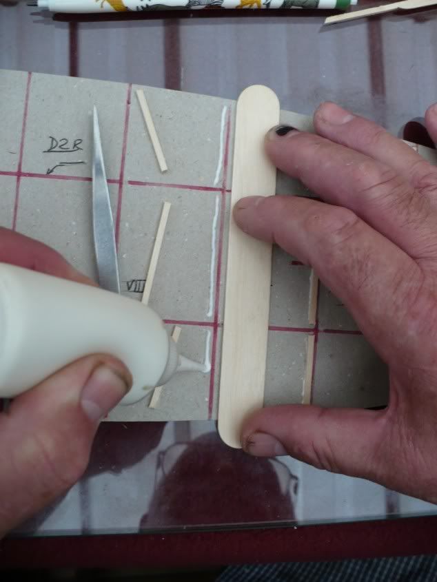
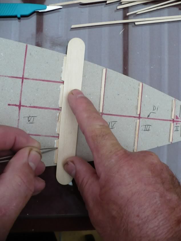
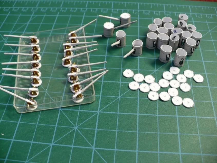
I also wanted the 138mm gun turrets to swivel.
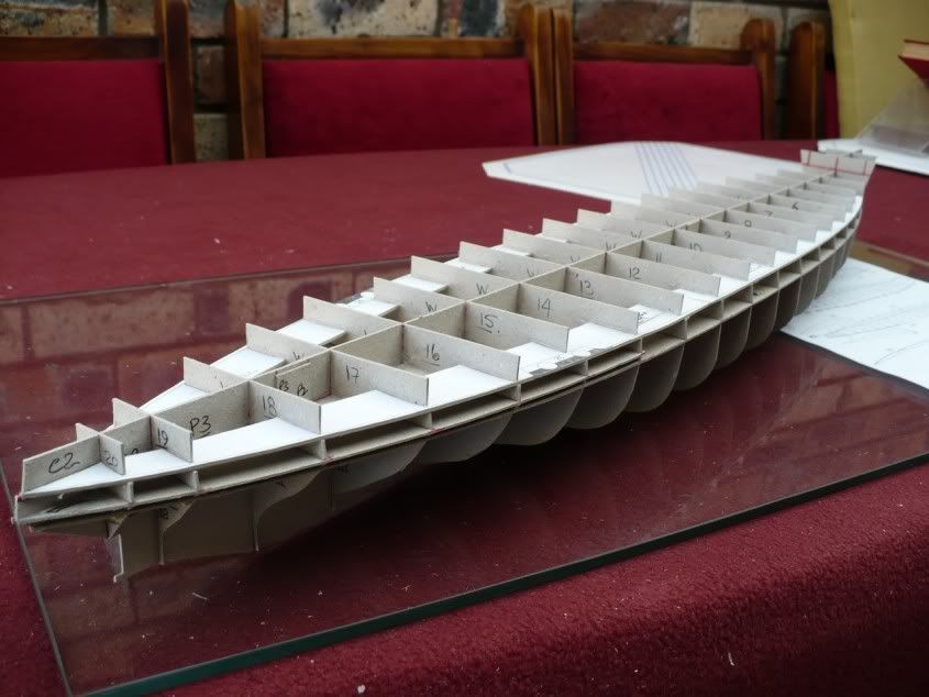
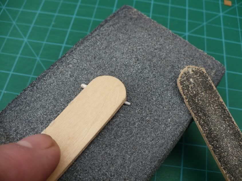
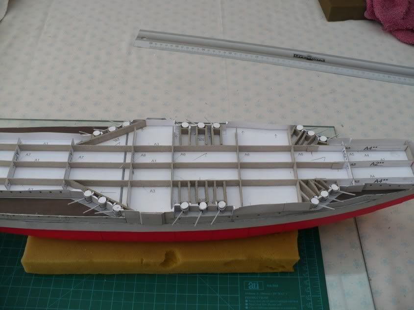
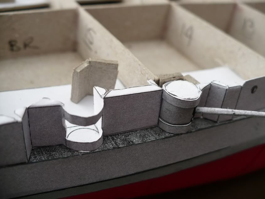
The instructions say to put pins in the centres of the top and bottom of the turrets to enable them to swivel but this would have been a mission to align the deck when gluing it over the turrets. A far easier and simpler solution was to make a “cage” from thick card around the rear of the turret. This worked great and the turrets swivel perfectly.

Swivelturret.jpg


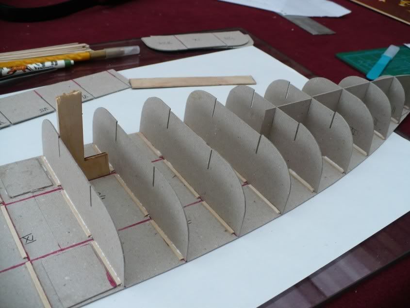
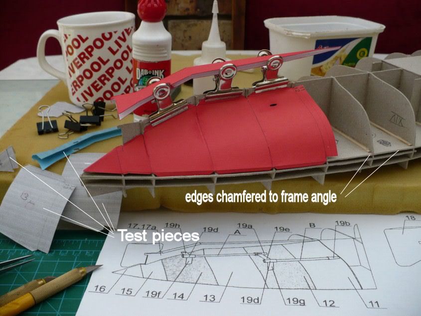
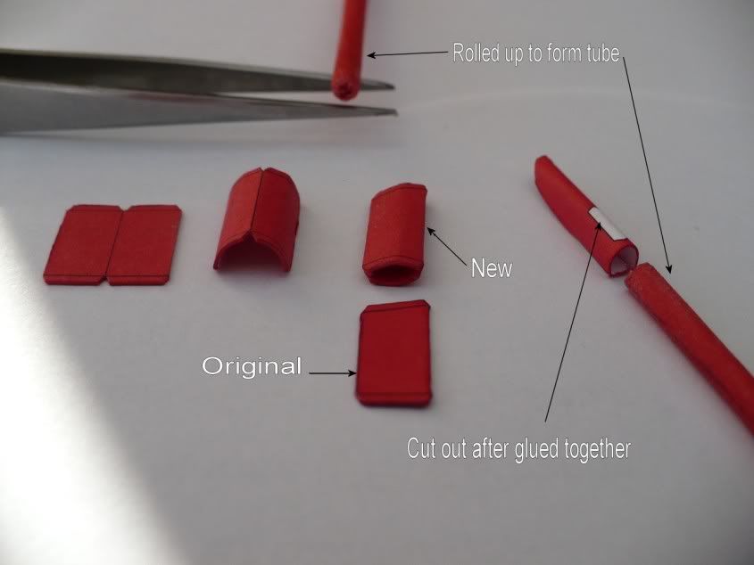
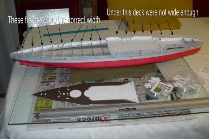
I am also beginning to find that some parts need “tuning” to fit. The bands around the turrets nearest to the centre of the ship on both sides were not long enough and I had to make new ones from one of the spare pieces of coloured card supplied. Also, the frames under the rear deck came flush to the edge of the deck but the frames under the forward deck were not wide enough so the deck overhung the frames along each side. The hull sides were supposed to glue to the frame edges and the deck edge and finish level with the top surface of the deck. This was solved by gluing small squares of card against the frame edges to bring them flush with the edge of the deck. The hull sides were then glued to these packing pieces and the deck edge.
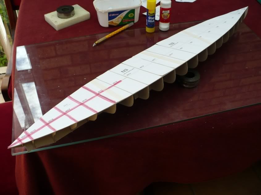
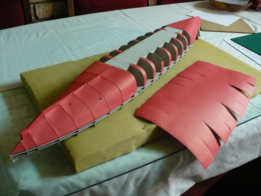
Here is the completed hull with first deck in place forward.

Framewidth.jpg


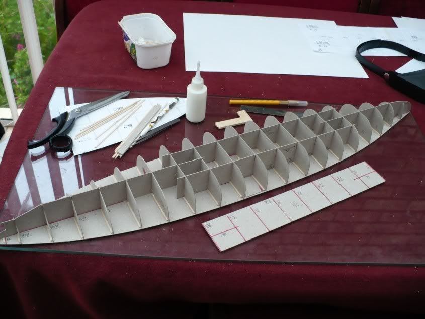
Normally, I assume the deck should go on first and then the sides are glued to it and the supporting frames. On this model however, because of the 138mm gun turrets recessed under the decks, the side pieces have to go on first and then the deck fitted afterwards.

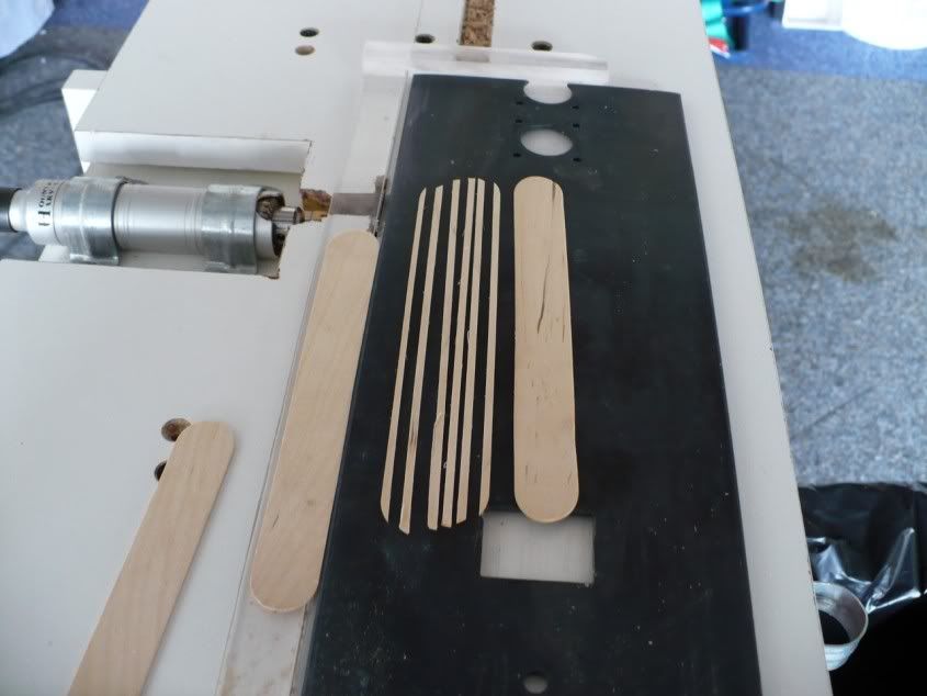
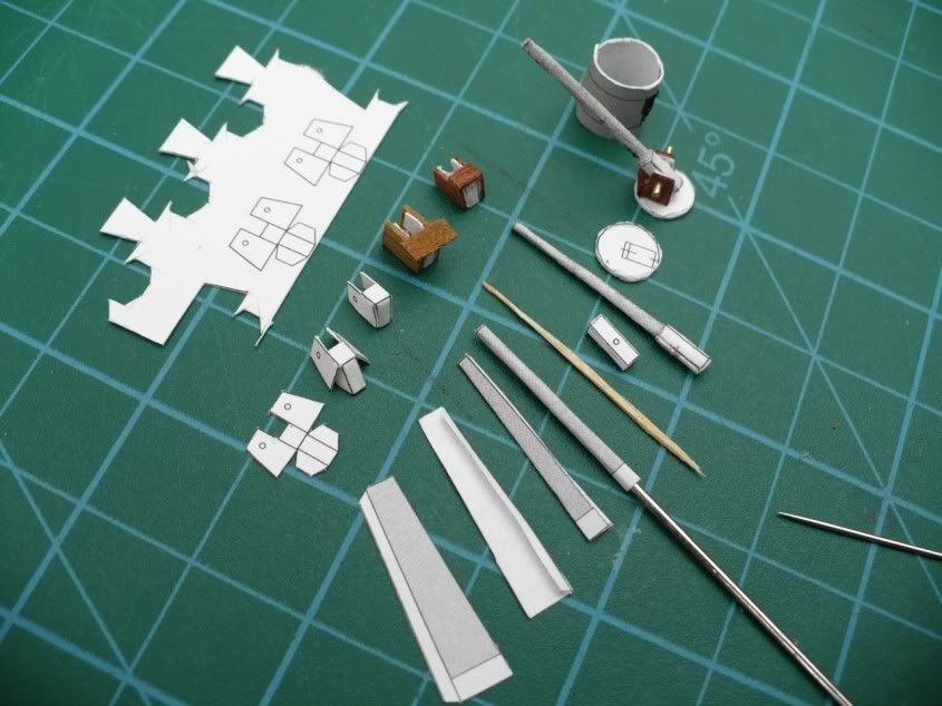
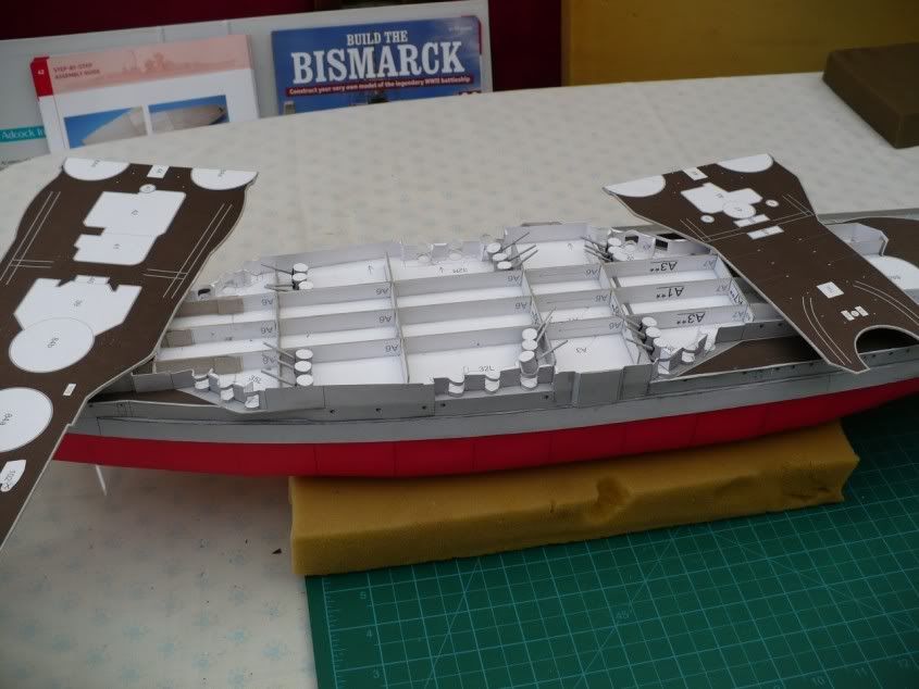
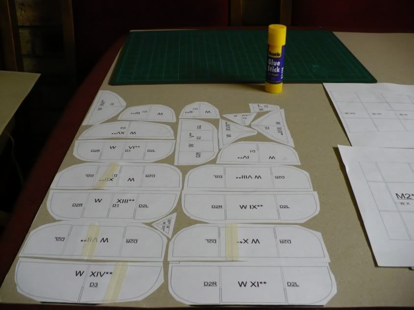
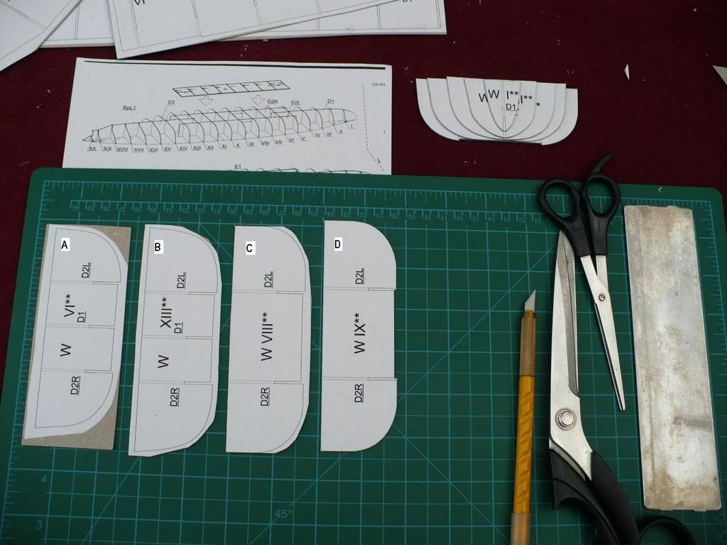
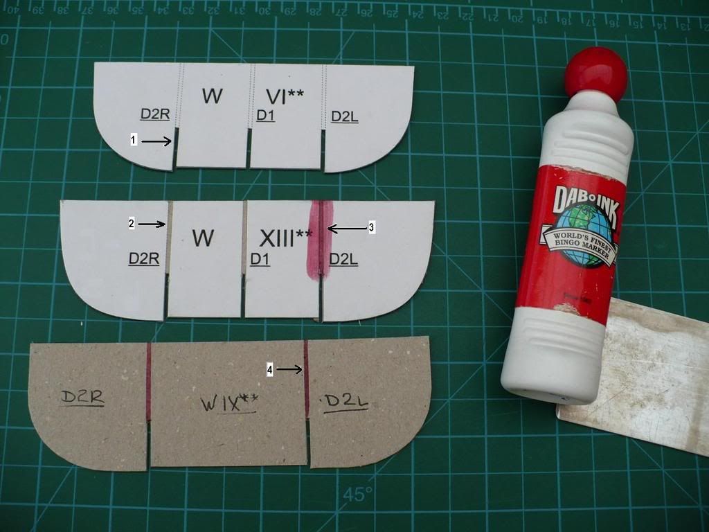
Lower deck 138mm gun turret positions

Lowerdeckguns.jpg


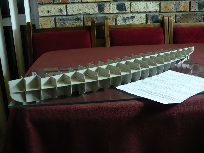
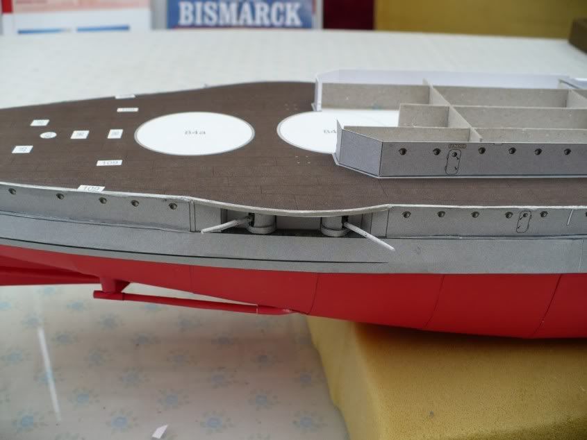
Upper deck 138mm gun turret positions.

Upperdeckguns.jpg


Upper deck gun cages.

Guncages.jpg


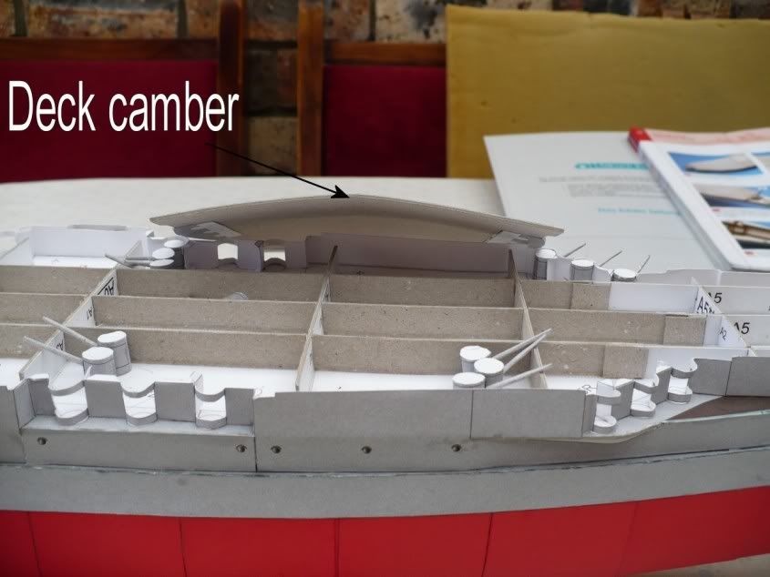
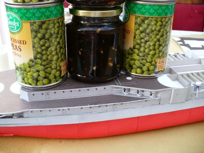
The decks were such a tight fit that they had to be “sprung” into position. This was done by bending the card decks along the centre axis to give a serious camber to the decks. This meant that the deck width was then less than the distance between the sides. PVA was then applied to the deck supporting frames and hull side edges and the deck sprung into place. The deck was then weighted with food tins to flatten it so that it fitted against the sides and was in contact with the supporting frames underneath.

Deckcamber.jpg


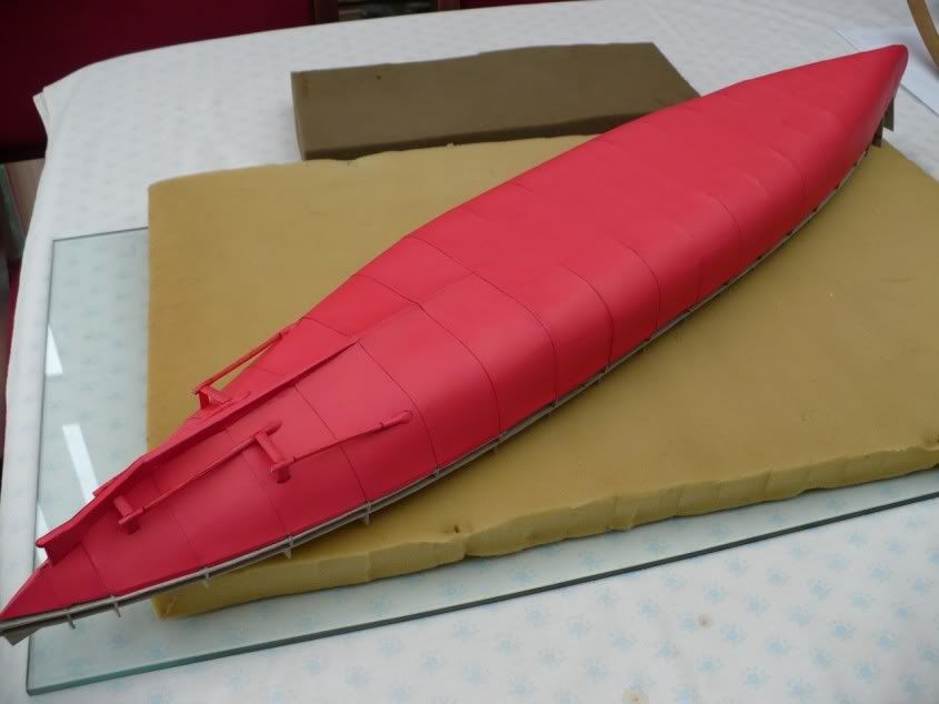
Here is the fore deck fitted.

Foredeck.jpg


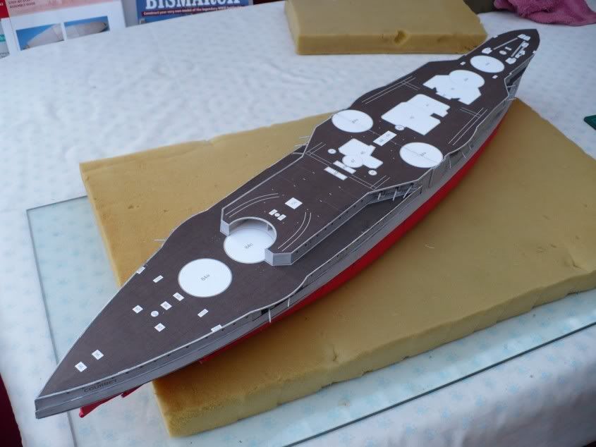
And finally, the completed hull.

Completedhull.jpg


I have come to the conclusion that card modellers are masochists!
 

lriera

Member
Aug 28, 2007
183
0
16
70
Barcelona - Spain
I can't agree more with you. We are a rare mutation of the apes. Not worst, not better, simply different, I think. But for sure, not dangerous and very creative and friendly.