How to Wire My Track

60103

Pooh Bah
Mar 25, 2002
4,754
0
36
Brampton, Ontario, Canada
Visit site
Cadflyer:
insulating one or two rails is a long debate. If you're going to grab one side of the DPDT switch for the lights, you will have to use common rail with single gaps (or connect all the north rail feeders together).
If you have one power pack with 2 controllers, there is a further problem: if they have a common transformer, common rail will create a short when one of them is reversed. With independent transformers, it doesn't matter and you can actually use common rail to run trains between controllers.
 

RonP

Member of the WMRC
Gary S. said:
Take a look at this link for some basic wiring. Towards the bottom, it shows some diagrams for dual cab control. See if that helps any, then get back with us.

http://retailers.kalmbach.com/tss/objects/pdf/12403spread.pdf

Also, it seems that the Tech II has a DC 12 volt accesory supply, so you don't need to worry with a bridge rectifier or diode to convert AC to DC.

You are a gentlemen and a scholar any more links to share ?
 

Cadflyer

New Member
Nov 8, 2006
8
0
1
54
I will check out that website(my pc is painfully slow on dial up). I have no intention of running two trains at the same time. Although i have a dual cab controller i have always only used one side. I have never used both controls. My layouts have always been partial to the use of only one cab. This current layout is the first one i have ever done with this level of wiring complexity. I had intentions of using the acc. side of the transformer for all of the lighting in my building structures. But, it apppears that won't be that easy to do with the intergration of the led's and such. I realize that this is not rocket science but i have never attempted any thing like this before. It is slowly starting to "click" with me as i continue to read and absorb the information in these post that everyone is providing. I truly appreciate everyones input on this.
 

Cadflyer

New Member
Nov 8, 2006
8
0
1
54
WOW, Thanks for the website. That pretty much makes everything clear to me now. The only thing i am still not 100% sure of myself about is hooking up the led's and resistors. I will continue to review this website and it appears that with all that info i should be able to complete my wiring. Over the next few days i will try to get a photo of my layout and a photo of my lighted control panel posted. Maybe that will help clarify what it is I am trying to accomplish.
Thanks again,
ZM
 

Cadflyer

New Member
Nov 8, 2006
8
0
1
54
ok, i tried hooking this up as a test and everything worked except the led will not light when the track is hot, it only lights when the throttle is advanced and the loco starts moving. What did i do wrong? My switches are SPDT. they have 3 terminals on the bottom.
Thanks,
 

YmeBP

Member
Dec 3, 2006
529
0
16
51
Southern New Jersey
www.skyersfamily.com
aussie Thank you soooo much. Sometimes i think i'm a bit touched and i need to see things to understand the words .. i use the fat crayons and my helmet i wear on the bus to work needs to be changed every 3 months so ... I truly appreciate the info in this page and on this thread...

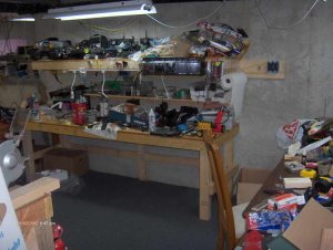
I've attached a photo of 1 and 3/4 of the work area's in my basement. Now i can proceed w/ clearing them up :).

Gary S. said:
Take a look at this link for some basic wiring. Towards the bottom, it shows some diagrams for dual cab control. See if that helps any, then get back with us.

http://retailers.kalmbach.com/tss/objects/pdf/12403spread.pdf

Also, it seems that the Tech II has a DC 12 volt accesory supply, so you don't need to worry with a bridge rectifier or diode to convert AC to DC.
 

Attachments

  • HPIM4985_resize.JPG
    HPIM4985_resize.JPG
    44 KB · Views: 203

pgandw

Active Member
Jul 9, 2005
1,002
0
36
Cadflyer said:
ok, i tried hooking this up as a test and everything worked except the led will not light when the track is hot, it only lights when the throttle is advanced and the loco starts moving. What did i do wrong? My switches are SPDT. they have 3 terminals on the bottom.
Thanks,
In your earlier post, you mentioned DPDT toggles. The circuit was designed for that, with the assumption that one pole would control the track section, and the other would control the LEDs. Each pole (the P in DPDT) of a toggle (or other switch) actually represents a separate switch thrown by the same handle. The LEDs cannot share the same wiring as the track power, as you have now wired it. The LEDs are presently turning on with the track power, and not working on their separate power supply as intended.

Your train requires a variable DC voltage; the amount of voltage determining the speed at which it will run. Light bulbs or LEDs (doesn't matter which) require a fixed voltage and current to stay at a constant brightness. This is why the LEDs or lights are powered from your accessory terminals, and not from the cab terminals. Because the lights are powered separately, they must have a separate pole on your toggle switch so that you do not mix the power. You need DPDT toggles, and to wire them as per the diagram. Since you don't use Cab B, you can and should omit that portion of the wiring diagram.

If you use LEDs, you must use a current limiting resistor (1K suggested) and the rectifier (or a least a diode) to convert the acessory terminal AC into DC. If you don't want to bother, use 16 volt light bulbs, and omit the resistor and rectifier.

Contrary to what some psoters have implied, if you have a Tech II 2800 (the dual control model in the Tech II series), the only accessory terminals are AC.
 

Gary S.

Senior Member
Oct 13, 2005
1,576
0
36
Texas
pgandw said:
Contrary to what some psoters have implied, if you have a Tech II 2800 (the dual control model in the Tech II series), the only accessory terminals are AC.

Oops, sorry, :eek:ops: that would be me. I must have looked at the wrong model on the website. My apologies for the misinformation.
 

JR&Son

Member
Dec 26, 2006
106
0
16
59
Near the NCVA RR
Sounds like you wired of the wrong side of the Power Supply.

With that said...
Ill muddy the waters....

I would not run DPDT switches
Personal choice here, but relays would and could do LOADS more

You do not REALLY need resistors, you need a voltage regulator
In this case the resistoris the regulator.
The only other thing I can add would be that not all LEDs are the same voltage and some are multi colored


Like I said, just to muddy the waters.

JR&SON
 

Santa Fe Jack

Member
Jul 20, 2006
253
0
16
63
Lost Almost, New Mexico
I am designing the same sort of thing, here, but with the added complexity of multiple controllers (up to 4) and 11 track blocks. I wish to have each block set up with 4 indicator lights (LEDs of different colors) so that I can tell at a glance which cab is controlling the block.

What I learned so far:

- Each color of LED has a different resistance, and so requires a different resistor to keep it happy at 12 V.

- No one makes a switch that will serve two wires to the block fed from two wires from each cab AND similar pairs of wires for the LEDs, too.

- This can work ONLY if I use common rail wiring. If I do that, then I need only switch one wire each for the track power, and one wire each for the LED power. A rotary 6-pole dual "throw" switch will work, and these are available at Radio Shack for $3.

Now what I need to find are wide-angle LEDs that come in four colors. Probably white/green/red/yellow, as blue is harder to find. The blue LEDs require more power (or put out dimmer light) since they are working at a less "visible" wavelength, I think.
 

boppa

Member
Jul 21, 2002
98
0
16
australia
au.geocities.com
JR&Son said:
Sounds like you wired of the wrong side of the Power Supply.

With that said...
Ill muddy the waters....

I would not run DPDT switches
Personal choice here, but relays would and could do LOADS more

You do not REALLY need resistors, you need a voltage regulator
In this case the resistoris the regulator.
The only other thing I can add would be that not all LEDs are the same voltage and some are multi colored


Like I said, just to muddy the waters.

JR&SON


um actually using a voltage reg without the resistor is a BAD idea
the voltage reg does exactly that - holds the voltage at a certain voltage (ie 7805 at 5v, 7812 at 12v )
the resistor in a led series circuit does drop the voltage yes- but its primary job is CURRENT limiting
most(not all tho) leds require at most 25mA and depending on colour a forward voltage between 1.2 to 3 volts

you normally get a data sheet from where you bought the led that has Imax(current) and forward voltages listed on it
you then use a formula to calculate the correct resistor on it

(dont know how well this formatting will work for the formula)
(Vsupply - Vled)
----------------------- = Resistor value
(Imax * 1000)

where the resistor value is in ohms
Vsupply is the voltage from the power supply
Vled is the forward voltage listed for your led in volts
Imax is the current listed for your led in mA

this is very unlikely to be an actual resistor value (only certain values are available in each range) so you look at the values available and use the next HIGHEST value closest to your calculated figure

eg you calculated you need a 557 ohm resistor -not available(there are good technical reasons for this which i wont bother to explain at the moment)
in the most common range available the next highest available value would be a 560 ohm resistor- thats what you would buy - not the 520 ohm

for leds a 1/4w is quite ok- but a 1/8watt can be used if space is really tight(ie in a loco shell)