How to Wire My Track

Cadflyer

New Member
Nov 8, 2006
8
0
1
54
I am building a somwhat large layout with numerous dead end sidings and turnouts. I want to isolate most all of the sidings and turnouts because i will have several locomotives staged along these areas of my track. I have purchased a dozen or so DPDT toggle switches. I am wanting to wire each piece of isolated track up so i can power on/off with the flip of a toggle switch. In addition to that i want to install LED's onto my control panel track design so i can see which tracks or "hot" as i am operating the layout. I want to LED's to be lit when hot and NOT lit when dead. I am seeking someone who can point me in the right direction as to how i am can wire all this up and do i need to also install resistors between the LED's and the switches??
Thanks
ZM
zmethvin@sbcglobal.net
 

Cadflyer

New Member
Nov 8, 2006
8
0
1
54
wiring

I am using TECH II Dual DC controller. What resistors do i need and how do i wiring the resistors, switches and LED's all together???
Thanks,
 

Gary S.

Senior Member
Oct 13, 2005
1,576
0
36
Texas
Relying on my rudimentary knowledge of electronics and electricity....

An LED is a Light Emitting Diode, as such, it is number one a diode. A diode is nothing more than a directional switch. It allows current to flow in one direction but not the other. The LED is simply a special type of diode that emits light when it is biased, or polarized in the proper direction.

Now, a basic electric circuit requires a minimum of three things. A source, a load, and conductors to connect them. The source supplies the electric current, the conductors carry the current to and from the laod, and the load limits the amount of current flowing.

Sources can be batteries, generators, power packs, etc. Loads can be light bulbs, motors, heating elements, etc.

A fourth element can be added into the circuit, that is something to turn the load on and off, namely a switch.

So, we can have the source, a switch, a load, and the wires hooking them together.

Now, diodes happen to fall into the "switch" category because they do not significantly limit the amount of current flow like a load does. Even though an LED emits light, it still doesn't act like a normal light bulb in limiting the current. The LED is not considered as a laod. It is a switching device. Adding the resistor to the circuit is simply a load to limit the amount of current through the diode.

An properly biased LED connected across a voltage source without a load will be a short circuit and will probably burn out the LED due to high current flow.

LEDs have an inherent voltage rating depending on the type of material it is made from. This voltage rating is very low, like .3 or .6 volts or so. If they made a 12 volt LED, it would have to have a built in resistor. I don't think any manufacturer does this, but they could.
 

Gary S.

Senior Member
Oct 13, 2005
1,576
0
36
Texas
Let me elaborate a bit more. Diodes actually have 2 voltage ratings. The one that they put on the package is the "reversed bias" voltage, or "peak inverse voltage". That is how much voltage the diode can block when hooked up backwards to the polarity. The forward biased voltage drop is as I mentioned, only .3 or .6 volts somewhere in that range. And since the LED emits light only when forward biased, that less than 1 volt drop becomes important, and we need the resistor. Properly sizing this resistor is easy using Ohm's Law and simple arithmetic.
 

Gary S.

Senior Member
Oct 13, 2005
1,576
0
36
Texas
Cadflyer, I am fairly new to trains and haven't used DC, but here are my thoughts, hopefully one of the old pros will jump in with some other thoughts and bail me out of this.:eek:ops:

First, to power the LED, we won't be able to use track power from your controller because it will change polarity when you use the direction switch, plus the voltage level will be going up and down as you speed up and slow down your train. Also, if the train is brought to a stop, the track voltage will go to zero.

Does your controller have any "accessory" terminals and what is the voltage rating and type? DC or AC?
 

Cadflyer

New Member
Nov 8, 2006
8
0
1
54
Wiring

Thank you so much for all this information. However, you are bascially speaking greek to me. I know nothing about this type of electronics. I may just use a standard light instead of the led's. I am starting get the feeling that would be alot easier. I am about to take a trip to the Radio Shack here and see what all they offer in the line of mini lights and such. All I want is a small light that comes on when a particular block of track is hot. I really do appreciate all of your help.:thumb:
 

Cadflyer

New Member
Nov 8, 2006
8
0
1
54
Sorry, My controller has a Cab "A" Cab "B" and an accessory. It is a DC Controller.
 

Gary S.

Senior Member
Oct 13, 2005
1,576
0
36
Texas
What voltage are the accesory terminals? AC or DC?

You could hook a regular light bulb of the proper voltage across the tracks of each spur, but then the lights would dim or get bright as you varied the speed of your train.

Ignore that mumbo jumbo about the diodes. Using LEDs is easy enough.
 

who_dat73

Member
Jan 18, 2005
330
0
16
50
Minnesota
The way I did mine was go to wally world and buy a basic on/off switch I run it out of one terminal on the power pack to the switch then out of the other to a insulated rail on the track as far as the lights cant help much there but hope this helps !
 

pgandw

Active Member
Jul 9, 2005
1,002
0
36
Cadflyer

I'll try to keep this simple, but diagrams are easier. I have neither the talent not the time right now to make you a nice wiring diagram.

As far as LEDs go, just accept the fact that they need a resistor in line with the LED to keep the magic smoke inside. They also need DC to operate properly.

Regular light bulbs can be used instead of LEDs with less hassle, but they consume more power and are hot to the touch. A properly wired LED lasts nearly forever, but light bulbs burn out.

The parts you need (using LEDs) to accomplish what you want:

- A full wave rectifier or bridge rectifier. Used to be easily found at Radio Shack. You want a 1 amp, 50 PIV rating. You hook this to the accessory terminals of your power pack to turn the AC into DC. A 1 amp full wave bridge will power 50 LEDs, which is about all the accessory terminals on you power pack are good for.

- A 1K, 1/4 watt resistor for each LED. You hook this in series (end-to-end) with the LED. Doesn't matter which end it goes on, but it has to be there.

- an LED, green or red take your choice. If you use white, you may need a smaller resistor (never less than 500 ohms) to get enough brightness.

The track power routes through one side of your DPDT switch. I assume your power toggles have center off position. The LED power routes through the other side or "pole" of your DPDT switch. On the underside of the DPDT switch are 6 terminals. The 2 center terminals go to the track and to the LED. On the side with the track feed, Cab A power goes to one corner and Cab B to the other corner on the same side. Be consistent which corner goes to A and which goes to B so that flipping the toggle a given direction achieves the same result, no matter which track you are controlling. LED power (one wire) from the full wave bridge goes to both corners on the LED side of the toggle switch. That way the LED lights no matter which Cab is supplying power to the track. The other full wave bridge wire goes to the far side of the LED and resistor combination.

Done wiring the 1st toggle and LED? Great! Now make the track hot by flipping the toggle. If the LED doesn't light, then change the LED end-for-end. LEDs are polarity sensitive, so if the power is the wrong polarity, it won't work. Once you have established which way to wire the LED to give the correct polarity, wire all the other LEDs the same way.

Realistically, if you want to successfully put in wiring to control 2 trains, or want indicator lights, you will have to learn the very basics of electricity and DC circuits. Get a wiring book for beginners, and let the journey begin!

my thoughts, your choices
 

60103

Pooh Bah
Mar 25, 2002
4,754
0
36
Brampton, Ontario, Canada
Visit site
Is there any reason you can't use a 1.5v battery with an LED? I think most LEDs work off 1.5v.
If you have a 12V LED, there's probably a resistor in it.
Do you want to use the switches to choose the cab on the power pack as well? Are they center off of just 2 position?
 

YmeBP

Member
Dec 3, 2006
529
0
16
51
Southern New Jersey
www.skyersfamily.com
Where were you 16 years ago when i failed this part in shop class in school!? I actually understand it :), and w/ the oterh posts i understand a bit more (though not totally) about the load side and watt (tee hee couldn't resist(or) hhahhehe) math i need to apply.

SO ... I think i'll be browsing through the mouser catalogue to find me some led's. I actully remember how to read the strips (w/ the help of wikipedia) on the resistors to rate them.

I can't believe i actually understand it :) you have no idea how signifigant a breakthrough this is. I mean .. i'm pretty dam psyched ... bounce7 i mean that .. thanks!! I'll have to show you a picture of my bench w/ all the projects you've just helped on to completion ... seriously. After dinner i'll post.

Gary S. said:
Relying on my rudimentary knowledge of electronics and electricity....

An LED is a Light Emitting Diode, as such, it is number one a diode. A diode is nothing more than a directional switch. It allows current to flow in one direction but not the other. The LED is simply a special type of diode that emits light when it is biased, or polarized in the proper direction.

Now, a basic electric circuit requires a minimum of three things. A source, a load, and conductors to connect them. The source supplies the electric current, the conductors carry the current to and from the laod, and the load limits the amount of current flowing.

Sources can be batteries, generators, power packs, etc. Loads can be light bulbs, motors, heating elements, etc.

A fourth element can be added into the circuit, that is something to turn the load on and off, namely a switch.

So, we can have the source, a switch, a load, and the wires hooking them together.

Now, diodes happen to fall into the "switch" category because they do not significantly limit the amount of current flow like a load does. Even though an LED emits light, it still doesn't act like a normal light bulb in limiting the current. The LED is not considered as a laod. It is a switching device. Adding the resistor to the circuit is simply a load to limit the amount of current through the diode.

An properly biased LED connected across a voltage source without a load will be a short circuit and will probably burn out the LED due to high current flow.

LEDs have an inherent voltage rating depending on the type of material it is made from. This voltage rating is very low, like .3 or .6 volts or so. If they made a 12 volt LED, it would have to have a built in resistor. I don't think any manufacturer does this, but they could.
 

Gary S.

Senior Member
Oct 13, 2005
1,576
0
36
Texas
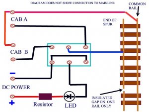
Here is a diagram of what my first interpretation of your idea is, and it seems to match Fred's idea. I don't know much about your DC control, for instance, if Cab A and Cab B already have a common terminal. To do this scheme with a DPDT for each spur, one rail has to be common to both Cabs (which it may already be).

For the DC source, you can use a fullwave bridge rectifier like Fred mentions (which interestingly is just four diodes connected in a precise configuration) or you could just use a single diode to produce half wave DC power which would also work, possibly the LEDs would be a bit dimmer.
 

Attachments

  • LED.jpg
    LED.jpg
    64.6 KB · Views: 421

Gary S.

Senior Member
Oct 13, 2005
1,576
0
36
Texas
60103 said:
Is there any reason you can't use a 1.5v battery with an LED? I think most LEDs work off 1.5v.

I gave it a try with a spare LED I had laying around. It wouldn't come on with a 1.5 volt battery. So, I figured maybe we needed a little more voltage, so I hooked it directly up to an old Tyco train transformer with no resistor in series. The LED came on at about 2.5 volts, and it looked okay for about 20 seconds. Then the magic smoke was released out of it and the magic ceased to exist inside. In other words, the LED was burned up.

Remember, the LED is not a load device. It is a switch that just happens to be turned on when it senses a certain level of properly biased (polarized) voltage. It is like closing a light switch. If you don't have a load in the circuit, the switch will let a lot of current through it. And most LEDs are only rated around 20 milliamps of current. Now, impoertant point ----> This does not mean the LED will only draw 20 milliamps - this is the maximum amount of current the LED can pass without burning up. The amount of current passing through the LED is not governed by the LED. It is governed by the load resistor.
 

Gary S.

Senior Member
Oct 13, 2005
1,576
0
36
Texas
Follow-up: If you had a current limited 3 volt supply, in other words, with a relatively high internal resistance, you could use it to supply an LED without a resistor. I'm experimenting right now with 2 1.5 volt batteries in series to see what that does.
 

Gary S.

Senior Member
Oct 13, 2005
1,576
0
36
Texas
The LED is still lit after 5 minutes on the two 1.5 volt batteries in series. It is getting warm to the touch.

Okay I give up. It was still on after 10 minutes. The deal is, the small batteries just aren't capable of putting out enough current to burn out the LED. For example, take a C cell 1.5 volt battery and take a wire and touch the positive and negative together... it doesn't even make a spark. But set your train controller to 3 volts and do the same thing... it will spark.

And it WILL burn up an LED!
 

pgandw

Active Member
Jul 9, 2005
1,002
0
36
Gary

Thanks very much for the diagram, that was exactly what I tried to describe with words. It would have taken me all day to produce that diagram.

A 3 volt battery supply generally works well with white LEDs (hence the LED flashlights), but depending on the battery output can be right on the ragged edge for keeping a red or green LED alive to see another day. Some type of regulation is needed for the red or green diodes - they have a smaller forward pass voltage than a white diode.

The other feature of a battery is that output voltage drops under load; the heavier the load the faster and greater the voltage drop. When cranking the starter motor in your car, your battery voltage can drop from 12.5 to 8 or 9 pretty quickly. Normal light bulb flashlights also dim pretty quickly becasue of the battery drain. The low current drain of an LED lets the batteries live a long time.

Thanks again for the diagram
 

Cadflyer

New Member
Nov 8, 2006
8
0
1
54
Thanks so much to all you guys. Ya'll have made this somewhat more clearer to me now. I currently have both rails insulated. Will this work or do i need to make just one side insulated? I recently got back from Radio Shack, i picked up (20) Led's and (20) 1/4-1k resistors. All of my switches are DPDT center off style. They have 6 terminals protruding from the bottom as common. At this point i have already installed the led's into my control panel schematic. I will have my switches on another panel next to the lighted panel. I felt it necessary to do it this way due to the room restriction i have. I also have to terminal blocks for multiple connections. I guess what i am needing is bascially a schematic like Gary shows. I am wanting to know how to complete this starting at my transformer. Check me here: transformer to terminal strip to switch to resistor to led and back to opposite side of switch ???