

Free FREDs...
- Thread starter shaygetz
- Start date
You are using an out of date browser. It may not display this or other websites correctly.
You should upgrade or use an alternative browser.
You should upgrade or use an alternative browser.
Thanks guys. Couldn't sleep 'til I knew I was back in the good graces of the pro-cabeese crowd. Now I'm wondering if I can charm a couple more out of the salesgirl for dome flashers on my GP35 and my Hustler. Wonder if they'll work off of a DCC decoder wired in with a resistor? This page keeps me too busy....
Originally posted by shaygetz
Thanks guys. Couldn't sleep 'til I knew I was back in the good graces of the pro-cabeese crowd. Now I'm wondering if I can charm a couple more out of the salesgirl for dome flashers on my GP35 and my Hustler. Wonder if they'll work off of a DCC decoder wired in with a resistor? This page keeps me too busy....
That's what I was thinking - Dome Flashers!!!
")
Great Stuff Shaygetz!!!
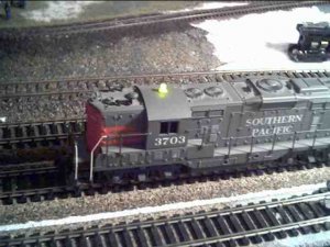
Dome flashers... The units work fine with off the shelf Radio Sham LEDs. just snip off the original, solder on a 3mm yellow one from their multi pack that's had its top filed flat, and wire it in like the others. It has a very pleasing effect, especially in low light, without the "fuzzy" glow of LEDs hooked up to decoders or the annoying giant yellow light bulb look of incandescents. Paint the base silver or the base color of your road and your done.
Attachments
Epilogue...
I was going to post the numerous ways I've used these circuits since I first set up this thread but felt it unnecessary as most can pretty much figure out their own uses with a little imagination and inginuity. However, the original device, while a crowd pleaser at shows, wasn't satisfying as a model, looking too much like an LED tacked onto a model freight car. Since that time, I've modified it slightly to look much more like a true FRED ---and--- it was relatively easy to do.
I bought an LED assortment from Radio Sham for $3. In it were several large red LEDs. Using a bench grinder, I squared up and reduced the LED's size, taking care not to remove any material around the element. It is much easier than it sounds, the red plastic falls away like glass leaving no burring of any kind.
I then cut a piece of shim brass for the face, drilling a 3/64" hole centered at the brightest point on the LED when lit.
Attachments
You'll also note that I did one of the small LEDs for the benefit of N scalers.
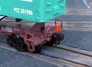
From this point, I took a dummy coupler and drilled two holes in it for the LED leads, just behind the knuckle. Then I painted it a base coat of silver everywhere except the small hole to prevent light bleed. I finished with a coat of safety orange followed by weathering (they take a pretty good beating in use). I soldered it in place of the old LED and mounted the coupler as per the original.
From this point, I took a dummy coupler and drilled two holes in it for the LED leads, just behind the knuckle. Then I painted it a base coat of silver everywhere except the small hole to prevent light bleed. I finished with a coat of safety orange followed by weathering (they take a pretty good beating in use). I soldered it in place of the old LED and mounted the coupler as per the original.
Attachments
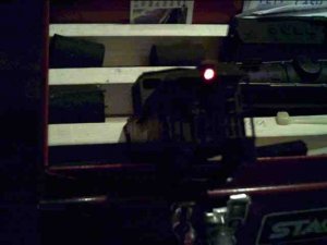
The finishing touch was a small drop of Testor's Clear Window Cement applied to the hole. This made a "jewel" that magnifys the brightness of the LED without making the hole too large. While the flash rate is 3x too fast, the overall effect is still quite pleasing.
Attachments
Still can't let them FREDs go...
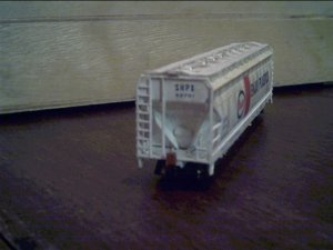
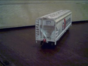
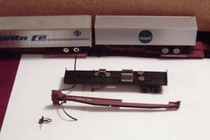
My latest install has me putting one on a 5 unit IMPACK car. I couldn't use regular batteries as they would make the car too top heavy. By making my own battery holders out of scrap styrene, I'm able to mount two 1.5v button cells inside a trailer with the flasher unit, thus keeping the COG low to prevent tipping on curves. The wire is snaked up thru the fifth wheel and into the bottom of the trailer where it is wired to a switch.
My latest install has me putting one on a 5 unit IMPACK car. I couldn't use regular batteries as they would make the car too top heavy. By making my own battery holders out of scrap styrene, I'm able to mount two 1.5v button cells inside a trailer with the flasher unit, thus keeping the COG low to prevent tipping on curves. The wire is snaked up thru the fifth wheel and into the bottom of the trailer where it is wired to a switch.
Attachments
Thanks, Jim.
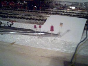
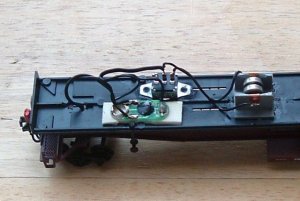
Here's the wrap up on this install. The final circuit is in and, as you can see is pretty basic. The only fussy part was the button cell battery box. It is a simple styrene affair, made to slightly larger than the batteries. The contacts are simple strips of brass with wire soldered to them then bent and glued to either end. The tension of the brass strips hold the cells in place. Unseen under the cells is a piece of I channel to help keep the cells centered and prevent them from rolling out.
Here's the wrap up on this install. The final circuit is in and, as you can see is pretty basic. The only fussy part was the button cell battery box. It is a simple styrene affair, made to slightly larger than the batteries. The contacts are simple strips of brass with wire soldered to them then bent and glued to either end. The tension of the brass strips hold the cells in place. Unseen under the cells is a piece of I channel to help keep the cells centered and prevent them from rolling out.
Attachments
Dude...Way to go! That's some heads up thinking "outside the box". Flexability is the key to airpower - and model railroading!
kf4jqd
Active Member
You can use flashing LED's (they hyave the flashing chip in them.) I think a few years ago, I posted them here on The Gauge. I do agree that I perfer the caboose instead of a FRED!
Andy
Andy
Thanks, Herc.
I'm familiar with those, Andy. By the time I had removed enough material off of the LED, it was still scaling out at 2' square, about 125% larger than I would like. This setup is only about 30% larger, thus sealing the doom of my caboose fleet.:thumb:
I'm familiar with those, Andy. By the time I had removed enough material off of the LED, it was still scaling out at 2' square, about 125% larger than I would like. This setup is only about 30% larger, thus sealing the doom of my caboose fleet.:thumb: