Finally started building.

KentBy

GN, NP, SP&S
Feb 1, 2008
97
0
6
Canby, Oregon
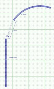
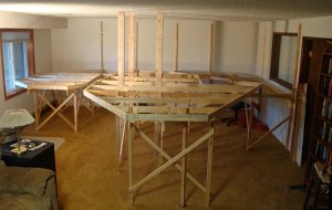
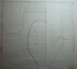
The framework is going up and I have a ruff sketch of the plan. I plan to have 24 inch curves on the main. I will have a small freight yard 8 feet long with four tracks.

I have some questions about this.

I think that I will space the tracks 2 inches apart. Is this good spacing? What number of switch should I be using?

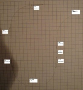
I have made a full scale template for the 24 inch curve. When I place the flex track should the center of the track go on this curve? What would be the correct number turn-out for 24 inch curve?

How would I make a template for the easement for 24 inch curve?

Thanks for your help.

Kent
 

Squidbait

Recovering ALCO-holic
Jan 27, 2007
1,219
0
36
58
Paris, ON
OK,

Personally, I think you're putting the cart before the horse by building your benchwork before you have a track plan. Unless you're building a 4x8 table, you're likely going to limit yourself to possibilities.

Before anyone can answer your questions (other than track spacing), we need to know how big a space you're planning for, what kind of equipment you're running (big/little steam, diesel? 86' hi-cubes and passenger cars or 40' freight cars?).

Good rule-of-thumb for track spacing is 2 1/4". Wide enough to get your fingers between pieces of rolling stock, narrow enough that the tracks look like they actually belong together.

You might want to consider playing with a track planning package like XtrkCad or RTS. XtrkCad will draw the easements in for you, and let you print out a 1:1 track plan you can paste onto your benchwork.
 

Squidbait

Recovering ALCO-holic
Jan 27, 2007
1,219
0
36
58
Paris, ON
Sorry, I'd never seen your other thread.

I'd stick to #6 turnouts or larger for the main, and nothing smaller than #5 in industrial areas. Anywhere you're going to run longer locos (big steam, 6-axle diesel) and long freight/passenger cars, I'd stick to #6's.

Your 24" radius should be the centreline of your track.

Rather than a template for your easements, just offset the curve template from the tangent track by 1/2", and allow about a linear foot or so from the end of tangent track to the start of the fixed radius curve. Then use a flexible piece of wood (like a yardstick) to connect the centrelines. It will give you a natural easment, and will look fine.
 

KentBy

GN, NP, SP&S
Feb 1, 2008
97
0
6
Canby, Oregon
Thanks again.

Lets make sure I understand correctly.

easement.jpg


Current state of layout is not to interesting but here is the table so far.

bench1.jpg

The plywood next to the edge is the yard 8ft x 10 inches.

yard.jpg

Kent
 

Squidbait

Recovering ALCO-holic
Jan 27, 2007
1,219
0
36
58
Paris, ON
I think you've got it. The offset (according to John Armstrong and XtrkCad) should be 7/16 or .44". The distance from the end of tangent to the end of fixed radius should be about 16". The distance from tangent to fixed radius (in my experience) doesn't need to be exact, so a ballpark is OK.

It's like this:
 

Attachments

  • easement.jpg
    easement.jpg
    121.2 KB · Views: 20

KentBy

GN, NP, SP&S
Feb 1, 2008
97
0
6
Canby, Oregon
Some more questions..

The bench work is almost done. I have 300 feet of code 83 flex track and am going to order some cork road bed and #4 custom line turnouts for the yards and #6 custom line turnouts for the main line.
The main line I will try to make 24 inch radius, but in some areas I may need to go to 23 inch radius. I will be wiring for DCC, but haven't decided which system yet.

Now the questions:

1. Anything wrong with what I have decided above?

2. Is the foam over the plywood is to reduce sound, has anyone tried gluing the foam under the plywood?

3. If I put 1 inch of foam over my yard, as I change elevation with my road do I continue to place the 1 inch of foam on the plywood road bed?

Thanks for the guidance, Kent.
 

Russ Bellinis

Active Member
Feb 13, 2003
4,501
0
36
78
Lakewood, Ca.
Visit site
1. As long as your curves are eased, most equipment that will work on 24 inch radius will also work on a 23. You may have difficulty if you try to run full length passenger equipment or 89 foot freight cars through the 23 inch radius, but they will probably have problems with the 24 as well.

2. I don't think foam is intended to reduce sound, it is just easier to sculpt for making small cuts or low hills in your terrain.

3. I'm not sure what you mean by the question.

By the way, off setting flex track going into a curve will also produce a natural easement.
 

KentBy

GN, NP, SP&S
Feb 1, 2008
97
0
6
Canby, Oregon
Thanks Russ

2. I don't think foam is intended to reduce sound, it is just easier to sculpt for making small cuts or low hills in your terrain.

3. I'm not sure what you mean by the question.

On 2. So do you cut the foam for the track road bed for elevation changes?

3. From my art (don't laugh) this is a side view of the yard with the track leading away. From the yard my road will increase in elevation. The art is not to scale. Is the top or bottom the correct way to do this? or something else?

Kent
 

Attachments

  • yard side view.jpg
    yard side view.jpg
    38.1 KB · Views: 13

Squidbait

Recovering ALCO-holic
Jan 27, 2007
1,219
0
36
58
Paris, ON
I'd just lay the foam over everything. Cut away the foam anywhere you want to dip below grade. It gives you a much easier to work with surface than the bare plywood.

If you haven't bought the foam already, you might consider 2"... gives you more room for dropping the scenery below grade level.
 

Russ Bellinis

Active Member
Feb 13, 2003
4,501
0
36
78
Lakewood, Ca.
Visit site
If you are using foam, put it on top like Squidbait said. Then for you roadbed, glue your preference on top of the foam. Then glue the flex track to the roadbed. I don't think the foam will hold spikes very well, but I've never tried it, so I don't know for sure. A bit of unsolicited advice on switches, switches become derailers if there is any twist or uneveness in the roadbed under them at all. Make sure whatever you use under your switches is "dead smooth" with no bumps or dips or anything that might introduce any sort of twist. Also let the switches sort of float. You can glue down the end of the track coming into the points and the two routes that are beyond the frog, but if you let everything float from the points through the frog, the switches will be more reliable. A nice flat piece of 2x4 6-12 inches long will make a nice sanding block to get your roadbed under switches dead smooth. If you are familiar with auto body work, you use the sanding block like a body man would use a "long block" for sanding ripples out of a body.
 

60103

Pooh Bah
Mar 25, 2002
4,754
0
36
Brampton, Ontario, Canada
Visit site
If you're using plywood under the foam, it's best to have a long flat piece before the grde starts and another long flat piece up the grade and let it bend in the middle. You need a very gentle bend -- much larger radius than you use for horizontal curves.
Another way is Woodland Scenics inclines glued on flat subroadbed. You still need to sculpt the change of grade at the bottom. I made a large grade this way but used foam to build up the bits below the incline. My mistake: the strips of 2% incline climb 1/2" but the 1/2" foam was actually 9/16" or 5/8" giving a lump. :curse: (look carefully before gluing!)
Another approach (not tried) is to cut the 2" foam sideways so the track is mounted on the cut edge, not the preformed surface. Needs a steady hand with the hot wire.
 

KentBy

GN, NP, SP&S
Feb 1, 2008
97
0
6
Canby, Oregon
Now for lighting

I have removed the light fixture that used to be in this part of the room. It was a 4 foot 4 tube fluorescent fixture in a wood framed box.
I am thinking about putting up track lights.

My current thoughts are to use lots of smaller lights on maybe two tracks 4 foot long.

The table covers about 17 x 17 foot area. Currently the light is just switched, but I though that I would convert it to a dimmer.

Any thoughts or advise on lighting?

Should I use longer track?

Any recommended sources for buying? I was thinking of just going to Home Depot.

Kent
 

Russ Bellinis

Active Member
Feb 13, 2003
4,501
0
36
78
Lakewood, Ca.
Visit site
Dimming works with incandescent lighting. Flourescent bulbs generally will be damaged if you try to dim them. The down side of all incandescent lighting is that they use a lot of electricity and produce a lot of heat. If you want to dim your lighting to simulate twilight or even night time running, but don't want to deal with a lot of incandescent light bulbs creating heat and using a lot of electricity, use a mix if both. perhaps a few incandescent bulbs with mostly flourescent tubes for fill light. To simulate evening, morning, etc. just turn off the flourescent lights, and then you can gradually dim the incandescent lighting. I've also seen people use blue flourescent tubes to simulate night time. In that case the daylight flourescent tubes are turned off, and the incandescents are gradually dimmed until they go out and the layout is now lit entirely by blue flourescent lighting.
 

KentBy

GN, NP, SP&S
Feb 1, 2008
97
0
6
Canby, Oregon
my table framework is done.

It didn't turnout exactly as I had planned. I needed to adjust in some areas for clearance. I will work on adjusting my track plan and post that when I have finished that.

Kent
 

Attachments

  • table1.jpg
    table1.jpg
    127.1 KB · Views: 6

KentBy

GN, NP, SP&S
Feb 1, 2008
97
0
6
Canby, Oregon
Diagram and a question.

Here is a diagram of the table framework. The room is 16.5 feet across the back and the middle part that sticks out is 15 feet from the back wall. The grid is 2 foot squares.

Now the question:

I have a drawn diagram of how I think that the track should be laid down. If I have a 24 inch radius and I want to have the plan that I drew than the following is true?

1. From the right bottom track (the start) I will need 24 inches from the right and 24 inches down. I need to add 2 12 inch section for easement and then 9 inches to keep from having an S turn. This means the I need 81 inches between the start to the bottom of the curve. I think that the 24 inch radius is measured from the center of the track, so I need to add 2 more inches to get from the top of Start and the bottom of the curve.

2. I guess that I only have the above question. Am I figuring it right?

Kent
 

Attachments

  • table diagram.jpg
    table diagram.jpg
    70.3 KB · Views: 69
  • curves.jpg
    curves.jpg
    81.7 KB · Views: 6