electrical question: latching relay

jdh

New Member
Jan 3, 2003
33
0
6
Visit site
quick question: is there a way to throw a latching relay the other way without reversing the polarity on the coil?
model is communications instruments, inc. #MQP17L DPDT [12v dc on the coil].

[bloody details follow]
I have been unable to find any data sheets on this animal.
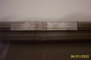
I have a simplistic wiring sticker that is smaller than a postage stamp, and it shows 1 coil and 2 coil wiring. I have been unable to get the 2 coil wiring to make any difference than the 1 coil. I am not sure that I can even use 2 coil wiring with this model. I am very confused about what pins 5 & 6 do.

The reason behind all of this is to power trackside signals via the same momentary switch that throws the points [solenoid powered]

Any ideas?
 

billk

Active Member
Jun 12, 2001
1,116
0
36
Marion, IA, USA
Just guessing, but if there is a two coil "mode", would you activate one coil to throw the relay one way and the other coil for the other way? Can you get a copy of the wiring diagram posted - that might help?
 

jdh

New Member
Jan 3, 2003
33
0
6
Visit site
here is as clear a pic as i can get.

pins:

5 6 <---- unknown
4 7
3 8
2 9
1 10 <---coil

4,3,2, are the contacts and feed for one side.
7,8,9 are the contacts for the other.

when 4 is hot, 7 is not
when 4 is hot, so is 9

when 7 is hot, so is 2
when 7 is hot, 9 is not.
 

Attachments

  • picture_1166.jpg
    picture_1166.jpg
    54.8 KB · Views: 199
Your photo isn't very clear, but it does show two coil latching. That would be one set of terminals to latch and the other set to unlatch. That means that all you have to do is hit the first coil with a momentary pulse to latch it and then another momentary pulse to the second coil to unlatch it.

Wouldn't it be easier to buy something that is a known quantity rather than trying to work with this?
 

tomfassett

Member
Oct 15, 2002
216
0
16
64
Chandler, AZ
www.trainweb.org
I gotta' go with Roger on this one. Besides, wouldn't it be better to have a control circuit that operated at layout voltages and low current? I have a lot of these types of big old brutes and I have pretty much abandoned them for the "smaller/cheaper/simpler" method. Here is a link to a circuit that uses inexpensive parts to make a standard off the shelf relay do the same thing:

http://www.railroadforum.com/forum/topic.asp?TOPIC_ID=742

A few post down there is a full diagram (schematic) for building two latching relay circuits with about $10 worth of parts. All of the parts are available from Radio Shack. You can also decide which kind of relay you want to use (small or large, depending on the current requirements of your switching circuit). I use 20 AMP relays so I never run out of juice...:D

Tom F
 

jdh

New Member
Jan 3, 2003
33
0
6
Visit site
Thanks for the reponses!

1) yes, it might be easier - but when i ordered these i WAS expecting a complete data sheet :(

2) this is not what you are remembering as a relay.
this is a solid state device, and is meant to be installed on a circuit board.

these are used in communication devices [radio transmitters, phone stuff, etc].

3) these run on 12v dc, physical size is 3/8" wide X 1/2" long.

thanks for the info about the 'latched and non-latched' pins, i had not thought of that.

i am still wondering how to either reverse polarity on the coil momentarily....
 
Originally posted by tomfassett
Here is a link to a circuit that uses inexpensive parts to make a standard off the shelf relay do the same thing:

http://www.railroadforum.com/forum/topic.asp?TOPIC_ID=742

A few post down there is a full diagram (schematic) for building two latching relay circuits with about $10 worth of parts

Interesting circuits. I'll have to take a closer look and see if there isn't something there that my railroad needs. :)
 
Hey jdh,
Have you had any luck?? This looks like it could be a really useful component. How much did they cost you and what is your source?? (if u don't mind me askin')
Like Roger, I think 1-10 is set (latch) and 5-6 is prolly reset (unlatch) both momentary inputs.
Can you post a clearer picture of the schematic??
 

Paul Davis

New Member
Like everyone else has said I think you need to momentarilly apply power to the coil. When you were doing you testing did you keep the power on the set coil? If you did then the reset would do nothing as you told it to set and reset at the same time.

Ayhow if you need a really simple circuit to give a pulse for the momentary coils then parallel a 4.7uF cap and a 10K resistor both in series with the relay coil. The values don't have to be exact.

If things don't work then:

#1 If the relay doesn't nothing or if it clicks but doesn't latch then the cap is too small.

#2 If the relay works but won't work again untill you wait a short amount of time the decrease the cap and/or resistor.

#3 If there isn't a pulse and the coil instead just stays energysed then increase the resistor.


For anyone who wants to know how the circuit works it's fairly simple. A discharged capacitor looks like a short. So when the switch if flipped current flows and energises the relay coil. However, this charges the cap. When a cap is charged it looks like an open so the coil is no longer energised. All the relay saw was a breif pulse. The resistor in parallel with the capacitor does allow some current to flow but it's not enough to energise the coil on the relay but is important for the next step.

Later on the switch will get back to it's original position. This won't affect the relay but affects the circuit as we could now be expecting the switch to be flipped on again to send another pulse to the relay. However, the capacitor is still charged so it still looks like an open. The resistor in parallel with the cap discharges it quickly so that it will once again looks like a short.

The same circuit wihout the resistor is still interesting. There will be a pulse each time the switch is thrown in either direction.
 

jdh

New Member
Jan 3, 2003
33
0
6
Visit site
thanks to everyone for their input.
i will try to answer everything in this post ;)

1. all electronics was the source.
http://www.allelectronics.com/

2. they are 2.00 each [part # LRLY-126]
coil=12vcd
1 amp contacts
1400 ohm coil
.35x.55x.2" [WxLxH]
DIP package, 10 pins made for a circuit board


3. no, i can not get a clearer picture, again the ORIGINAL sticker is so tiny you need a maginifying glass to see it in the first place.
[think n-scale car reporting marks for a comparison]

4. no joy on pins 5 or 6, again i am not even sure this section of the sticker applies to this component.

5. this thing does not click, nor is there any sensation of movement. this looks like a grey IC.

6. i really wish i could find a good data sheet on this :(

7. i can do a work around on reversing the polarity with a DPDT relay [a normal one], and since i have a box of those laying around i might go that route....

---

if i connect PINS 1 & 10 to the contact 'feeds' of the DPDT relay [backwards from what you would normally due - like for a reverse loop on your layout] i can then use one side of the latch relay to energize the normal relay's coil.

this reverses the current on the latch relay, thus letting me toss the thing back and forth.

granted, this is a brute force and ignorance method - but that is what i have to work with ;)

---
 

jdh

New Member
Jan 3, 2003
33
0
6
Visit site
ok, i forgot to answer the testing questions... [short buffer]

i tried momentary power on pins 1-10, 5-6, 1-5, 6-10
no joy on anything but 1-10
 

jdh

New Member
Jan 3, 2003
33
0
6
Visit site
for those of you wondering how i got into this...

i was looking for an electrical [not electronic] method to power several lamps indicating turnout position for atlas turnouts.

one lamp on control panel
one lamp [yellow] on up side 3 light signal [main facing side]
one lamp [red] on wrong down side signal [main opposing side]
one lamp [green] on right side signal [siding]
[four 14-16v lamps]

this would show that the turnout was thrown for the siding.

this leaves one red lamp [on the three light signal] left out.
i am using that lamp for block control signalling.

i thought about using a DPST wired via the control panel, but that would not be handy for walk-around control....
 
One side note-
Atlas now has an under-table switch machine with a snap-relay included (2 sets of contacts). I think the HO part is #66. :) :)
It's about the price of a tortoise.:eek:
This gives a truer indication of switch position, i.e., the signal follows the actual switch machine status, not just the pushbuttons. (FWIW)
 

jdh

New Member
Jan 3, 2003
33
0
6
Visit site
that is good to know about the HO atlas item.
i think they have a 'snap relay' that i could have used, but the price was something like 8.50 [each] ;)
 

tomfassett

Member
Oct 15, 2002
216
0
16
64
Chandler, AZ
www.trainweb.org
I say the info is on the relay somewhere. I have a couple of DIP mounted Communications Instruments Relays and they have a "rough" schematic on the top. The "coil voltage" inputs are usually across from each other, on one end of the device or the other. Try scanning the chip on a flatbed scanner if you have one. I do this all the time. Just lay the chip on the glass and scan each side. If that doesn't work, here is a phone number for Communications Instruments, Inc., that I got out of one of my data books. The book is a few years old so I hope the number is still good:

(704) 628-1711

Maybe they can let you know where to find a data sheet.

Tom F