EDITED By UP SD40-2: TUTORIALS on Installing Decoders/Sound Decoders

Status
Not open for further replies.

DanRaitz

Member
May 30, 2002
300
0
16
Maricopa, AZ, USA
UP SD40-2(Deano) said:
OK Folks, in lew of ALL the requests both in THIS section of the forum, and ALL the PM's i get for info on how to install decoders AND sound decoders in "different manufactures" engines, i have decided to make this thread up on how to do some of them:thumb:.

I WILL be adding tutorials to this as i get NEW engines, and if ANY you folks wish to do tutorials to add to this, just POST THEM and PM me, and i will add them to this thread:thumb:.

TO start this thread out Dan Raitz has done a FANTASTIC tutorial on installing a decoder in an Athearn Blue Box :thumb:. Dan has been GRACIOUS enough to let me use this thread he made for this:D, THANK YOU DAN!!!:D :D :D-Deano ** without further adieu, heres Dans tutorial;

I'm currently upgrading an older Athearn BB F45. Of course this means installing a DCC decoder. The first thing that I did was to remove the tangs from the bottom of the motor.

Athearnbottom1-1.jpg


Athearnbottom2.jpg


I then soldered wire to the motor clips and then covered the botoom with electrians tape.

Athearnbottom3-1.jpg


I then turned my attention to the trucks.

Athearntruck1-1.jpg

Athearntruck2.jpg


It was now time to assemble the chassis and hook-up the decoder.

Athearnchassiswithdecoder1.jpg

Athearnchassiswithdecoder2.jpg


DONE:) Now back to detailing this beast.
 

cnw1961

Member
Jan 7, 2006
846
0
16
65
Germany
Loksound for my VO-1000

UP SD40-2(Deano) said:
EDIT BY UPSD40-2: Folks, heres a GREAT tutorial Kurt done on installing LokSound in a Stewart brand engine:thumb: THANK YOU KURT!:D, for letting me add this tutorial to this thread!:D

I ordered a LokSound V3.5 decoder with Baldwin sound just after Christmas and it was eventually delivered today. Hey, it only took 2 1/2 months :rolleyes: . I installed the decoder in my Stewart Baldwin VO-1000. The Stewart diesels are DCC ready, that means, they have an 8pin NMRA plug. To install the LokSound decoder, I only had to remove the "blind" plug that is in place for DC operation and plug the decoder in – that’s all, no soldering, no jumpers etc.

The round 0.9" (23 mm) speaker that comes with the LokSound decoder is not suitable for this Baldwin. I ordered a 2/3" x 1" oval speaker that fits perfectly above the front truck, no modification to the frame needed. I glued the speaker face down to the frame. I didn’t use a special baffle for the speaker, I wanted the shell of the loco to act as a baffle. Without the shell, the sound is really weak, but it increases dramatically when the shell is in place. To close some gaps in the frame (and the "baffle"), I glued some styrene pieces to the frame. But I found out that it is not necessary to close those gaps, the sound is just as good without the styrene pieces.

vosound1.jpg


Only the LED retaining clip had to be modified. It touched the top of the speaker and hindered the shell to snap in . So I cut off the rear end of the clip (with the two pins that are used to attach the clip) and glued it to the shell.

vosound2.jpg


The sound is very loud (I turned it down to approx. 40 %) and as good as you can expect of such a small speaker. The motor control of the LokSound decoder is superb, the engine runs smoothly and can crawl very slowly.

So, if you are looking for a very well detailed switcher that runs perfectly and you want to install sound without any problems, the Stewart Baldwin VO-1000 is the right engine for you.

Deano, I hope this decoder installation gets your seal of approval. :D :wave: :wave:
 

Attachments

  • vosound2.jpg
    vosound2.jpg
    26.9 KB · Views: 356
  • vosound1.jpg
    vosound1.jpg
    51.7 KB · Views: 148

cnw1961

Member
Jan 7, 2006
846
0
16
65
Germany
Miles, if you don’t want to use a baffle for the speaker, it is very easy to install a LokSound decoder in your "Bricks". You can place the LokSound speaker above the rear truck and the decoder on top of the speaker. I would close the gap between the speaker and the motor/pc-board with a piece of styrene. It might enhance the sound. If you want to use the baffle that comes with the decoder, you might place the decoder on top of the pc-board or in the cab. But it would be a tight fit, so I cannot tell for sure if you can place the decoder there.

brick.jpg
 

Attachments

  • brick.jpg
    brick.jpg
    37.7 KB · Views: 360

UP SD40-2

Senior Member
Apr 29, 2006
2,709
0
36
58
Athearn RTR & GENESIS

OK FOLKS, of all the PM's i get for the "how to's" on installing decoders or sound decoders(they BOTH install the same way;) ), are for Athearn RTR's and Athearn Genesis, therefor :ANYWORD: HERE IS MY EASY FAIL PROOF decoder/sound decoder install:up: .

FIRST, i just want to say that I DO NOT install decoders/sound decoders this way in Athearn DCC ready engines:eeki: . I remove the Athearn circuit board to save room, and just "hot wire" the sound decoders right to the wires that remain after i take the circuit board out:mrgreen: . its really quite easy, but FOR THIS INSTALLATION, i will be showing you the EASIEST FAIL PROOF way that ANYONE could do the install LEAVING THE CIRCUIT BOARD IN:up: .

(for those that want to try the install as I NORMALLY DO IT, WITHOUT THE CIRCUIT BOARD, heres the wire set up:
orange wire- right side of motor
gray wire- left side of motor
red wire- right side of trucks
black wire- left side of trucks
white wire- headlight
yellow wire- taillight
blue wire- common wire for BOTH front and rear lights.):mrgreen:

The Sad Truth...
On MOST engines installing a decoder/sound decoder is so easy, it will take you longer to get the shell off, then actually installing the sound decoder:mrgreen: . P2k, Kato, and Stuart brand engines are just SOME that are REAL EASY to do decoder/sound decoder installs:up: , on those brands you would simply plug the 8 pin decoder plug into the 8 pin socket on their circuit board, and TA DA!! YOUR DONE!:mrgreen: On Athearn "DCC ready" engines...this IS NOT the case:( . the problem is Athearns "DCC ready" circuit boards 8 pin sockets are SO SLOPPY, you could NEVER just plug the decoders 8 pin plug into Athearns circuit boards 8 pin socket and think it will work:madd: :( .

On Athearns decoder/sound decoder install instructions it states: "solder the 8 pin plug to the 8 pin socket on the circuit board". MY answer to this? HA! GOOD LUCK WITH THAT:roller: . if you can actually do this, you are a WAY BETTER man then me:toug: . TWO things will happen,
1- the circuit board will melt:( .
2- good luck trying to NOT let the solder run from one pin to the other:( .

THE ANSWER...
I am going to show you how to install a decoder/sound decoder doing a "soft hot wire";) . following my instructions ANYONE can successfully install a decoder/ sound decoder into ANY Athearn "DCC READY" engine:up: :mrgreen: .
dec1.jpg


LETS BEGIN THE INSTALL:up: :
Since ALL my engines ARE SOUND EQUIPPED, i am going to show you how to install a sound decoder, HOWEVER, a regular decoder would install THE SAME WAY:up: .
FIRST- take the shell off the chassis, notice the 9 pin socket on Athearns circuit board.
dec2.jpg


Now what we are going to do is CUT OFF the 9 pin socket off of Athearns circuit board, when you do this, leave as much wire connected to the circuit board AS POSSIBLE. After that is done, CUT OFF the 8 pin plug connected to your sound decoder. LEAVE AS MUCH WIRE CONNECTED TO THE DECODER AS POSSIBLE. (see pic)
dec3.jpg


NOW, carefully bare the ends of the wires you have just cut off. NOTICE all the wires are color coded:up: . simply match the color coded wires on your sound decoder to the SAME color wires sticking out of Athearns circuit board, and solder them together:up: . (example: red to red)
dec4.jpg


After you have soldered each colored wire to its match, now you have to cover them SEPARATELY so NONE of the different colored wires touch each other, this would cause a short:eeki: . you could use shrink tubing to cover the separate wires, or electrical tape, OR, i use hot glue:eeki: , thats right, i said hot glue:up: . i have been doing this for years and have had no problems:up: . the choice IS YOURS, just be sure to cover the wires some how:) .

now that ALL the wires have been covered so the different colors DON'T TOUCH each other, i use a little hot glue and apply it to the plastic speaker cover and glue it to the cab roof, with the exposed part of the speaker facing down to the rails:up: . after that is done, put the shell back on and TA DA!!! YOUR DONE!!!:up: :headbang: :mrgreen:

NOW put the engine back on the track, PROGRAM IT, and ENJOY IT!!!:mrgreen:
dec5.jpg


I hope this will help those that have NEVER installed decoders/sound decoders in Athearn DCC READY engines, but wanted to:up: .
:mrgreen: -Deano
 

UP SD40-2

Senior Member
Apr 29, 2006
2,709
0
36
58
PROTO 1000 Sound decoder "Hardwire" install

BEFORE WE BEGIN...

I am going to show you folks how I do a "Hardwire" install.

What is a "Hardwire" install?:confused:

A "Hardwire" install is wiring a decoder, or in this case a sound decoder, into an engine.

We will be doing the hardwire installation because the engine that is getting the sound decoder DOES NOT have a DCC READY "Plug-n-Play" circuit board.

Though i am installing the sound decoder in a Proto 1000 engine, you can use this same exact type of install on ANY engine thats motor is already isolated from the frame, and does NOT have a Plug-n-play circuit board:winki: .

HOWEVER, you can use this type of install on "DCC ready" engines with plug-n-play circuit boards too, take Athearns "DCC ready" engines for example, their plug-n-play circuit boards are worthless:eeki: (in MY eyes), and i hardwire ALL my sound decoders into those engines. (i have wrote SEVERAL posts on this:winki: )

ANOTHER REASON to do a hardwire install would be to save space, in many engines there just isn't much room to add a sound decoder, so to save space you might need to take out the existing circuit board thats in the engine to give you room to install the sound decoder:winki: .

A SMALL DISCREPENCY...

I am installing a sound decoder into an FM CPA16 engine, Loksound makes real good quality sound decoders, thats sounds are really pretty much "right on" for the engine sound they offer:thumb: . the problem i am having with this engine is i use 6 resources to get my sound decoders from, and only one of the six had Loksound FM sound decoders in stock, the two FM sound decoders i had to choose from was the H10-44 and the H24-66 sounds, no CPA16/CFA16 sound decoders were available. i wanted to stay with the FM opposed piston sound, so i opted for the H24-66 sounds, its not right for this engine, but at least it has the FM opposed piston sounds:winki: .

LETS BEGIN THE INSTALL... :twisted:

TOOLS NEEDED:
Soldering gun
solder
hot glue gun
4'' piece of fine black wire
4" piece of fine red wire
thin strip of thick styrene
wire cutters
exacto knife
heat shrink tape
electrical tape

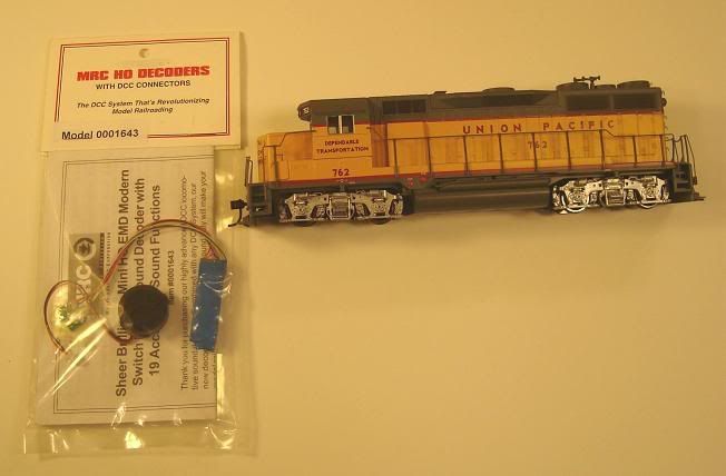
ALSO, the decoder or sound decoder of your choice, a set of DCC compatible lights, and of coarse, the engine to install it all in:toug::119: .

DSC02884.JPG


OK, now that we have ALL the materials together that we need, this install should only take 30-45 minutes, tops:thumb: .
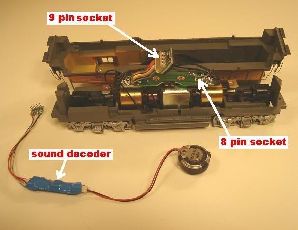
get your engine and sound decoder out, and familiarize your self with them...

DSC02892.JPG


DSC02893.JPG


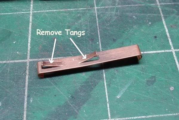
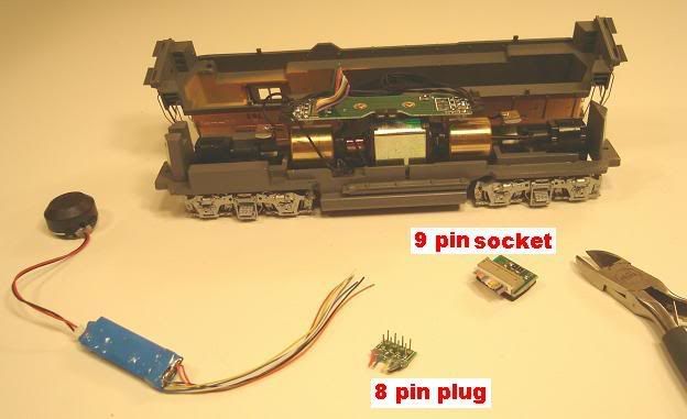
Now, cut the 8 pin plug off your sound decoder, exactly as i shown in the pic below, leaving plenty of wire still attached to the sound decoder...

DSC02900.JPG


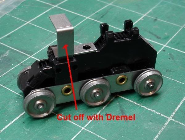
NOW disconnect the wires from the circuit board thats in the engine, and pull the circuit board out of it, also take the light/s out of the engine at this time...

DSC02903.JPG


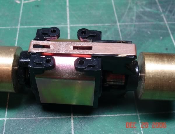
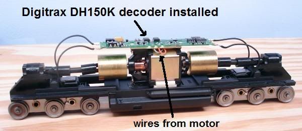
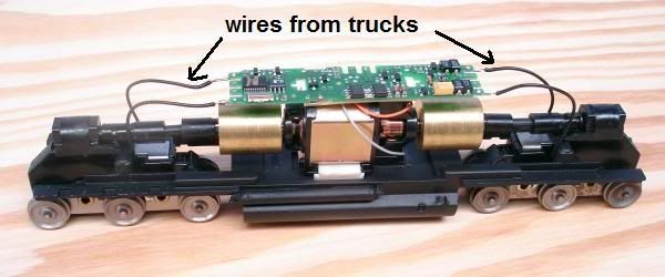
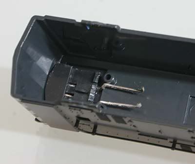
Now you see the only wires that are still in the engine are the four wheel power pick up wires, two red, two black, and the two engine power wires in the middle of the engine, one black, one red. (pic below)
At this time i make a little "shelf" out of a thick piece of styrene, what this does is gives you something to put the speaker and sound decoder on so none of it touches the hot motor, and it keeps the wiring from getting into the gears:winki: . i put two SMALL drops of hot glue on top of the flat part of the motor casing, let the glue almost dry, then put the styrene "shelf on it, DON'T press the shelf down hard on the motor, the drops of hot glue keep the "shelf" off the motor just a bit so air can get between the two, for cooling purposes:winki: . MAKE SURE THE SHELF TOUCHES NO MOVING PARTS.

DSC02916.JPG


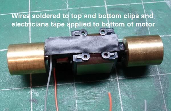
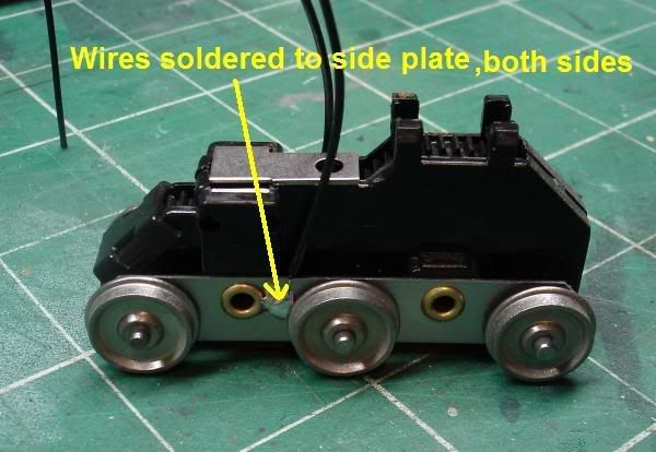
OK, NOW we are going to take the two pieces of 4'' wire we have(red and black), and we are going to make them "jumper wires" that will go between the left and right side wheel power pick up wires. (shown below)
**NOTE: YOU WILL WANT TO USE YOUR HEAT SHRINK TAPE TO COVER THE SOLDERED WIRES WHEN YOUR DONE, you will notice i don't use the heat shrink tape, i hot glue over my connections:eeki: , it does the same thing as heat shrink tape, but you have to be VERY CAREFUL and make sure ALL of the bare wire is covered, I DO NOT RECOMMEND doing as i do, PLEASE USE the heat shrink tape, WHY YOU ASK?:confused: , well if your reading this your NEW to doing "Hardwire" decoder installs, so don't take any chances do it right:winki: , leave the "tricks" to the pro's:toug::119: .

DSC02922.JPG


NOW that we have the wheel pick up jumper wires installed, we will take and bare the ends of the wires on the sound decoder that we are going to use:winki: . the wires on decoders/sound decoders are color coded, the codes for each wire color coming out of the decoder are:
RED- WHEEL CURRENT PICK UP #1
BLACK- WHEEL CURRENT PICK UP #2
ORANGE- RIGHT MOTOR WIRE
GRAY- LEFT MOTOR WIRE
WHITE- HEADLIGHT
YELLOW- TAIL LIGHT(no tail light on this install)
BLUE- THE COMMON WIRE FOR BOTH, THE HEADLIGHT AND TAILLIGHT:winki: .
GREEN- FUNCTION F1(we wont use this)
PURPLE- a function wire we wont use either for this install.
2 BROWN WIRES- speaker/s

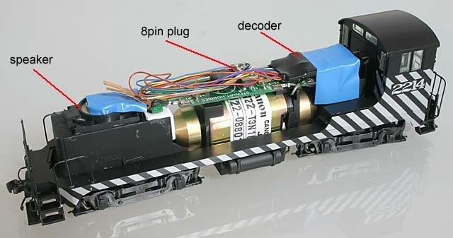
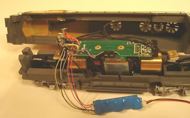
OK, going by the wire codes i have provided, and the pic i posted below this, solder it all up, don't forget to use your NEW DCC compatible light, and use heat shrink wire wrap to cover ALL the bare wires when your done.

DSC02938.JPG


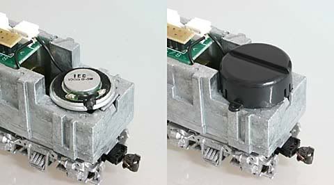
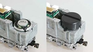
OK, now that we have it all wired up, re-install your light, neatly wrap up the extra wiring and tape it in place so it doesn't move around. (see pic below) at this time i take a drop of hot glue and put it on the bottom of the speaker baffle/case(NOT ON THE SPEAKER ITS SELF!:eeki: ), then place it on the styrene shelf...

DSC02942.JPG


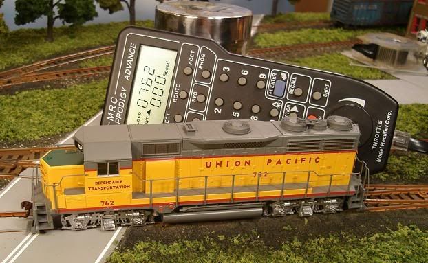
NOW place the engine shell back on its frame and...WE ARE DONE!
:thumb::thumb::thumb:

SEE, not hard at all:thumb::mrgreen:
Put the engine on your track, program it, and ENJOY IT!

I hope this helps some of you out:winki::smilie: .

DSC02960.JPG
 
Status
Not open for further replies.