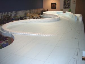
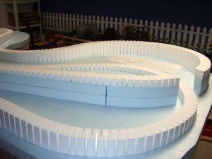
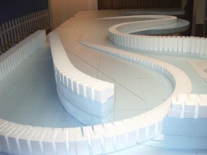
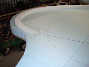
Don't laugh too hard...It's my first attempt!

pgandw

Active Member
Jul 9, 2005
1,002
0
36
Curved turnouts - at least the Walters/Shinohara and Peco seem to have no more trouble than regular turnouts. And they can save considerable space in tight situations. I would much prefer to use curved turnouts than drop my minimum radius below 18 inches.

Less than 18 inches will likely be trouble on your turntable approach tracks. Larger steam locomotives and 6 axle diesels often (but not always) have trouble with 18" radius curves, much less anything tighter. Again, I would sacrifice a turntable approach track or roundhouse stall rather than tighten radius there.

In the yard, a 15" radius will work with 40ft and shorter freight cars - but you cannot couple or uncouple on such sharp curves. Longer freight and passenger cars will not take kindly to less than 18" radius either. Rule of thumb is that 15/16" radius is pretty much limited to switching locomotives and 40ft or less freight cars in HO.

Another way to help yourself is to cut back the turnouts. Almost all commercial turnouts have extra track beyond the frog, and in front of the points. This can usually be cut back almost to the frog or points where/when needed without serious consequences.

yours in tracking
 

Nazgul

Active Member
Jan 22, 2006
992
0
36
63
Ohio
Fred, that's a wealth of useful information, thank you very much. I'll look into the better quality curved turnouts and see if cutting back on some will help. I would like to keep this layout as close to the original drawing as possible. Galen did such a great job on it and it has every thing I wanted. I think the curved turnouts will solve the problem.
 

ocalicreek

Member
May 4, 2005
824
0
16
48
Puyallup, WA
groups.yahoo.com
tight spots

Back when I first sketched the plan I was afraid the areas you've highlighted wouldn't be exactly as sketched. If you'd like I can plan out the layout with more accurate dimensions (I use a plastic HO template, mechanical pencil and graph paper...I'd like to get into a CAD program or layout planning software someday, but for now this works).

I had in mind #4 turnouts and flex track for the most part, with #6 turnouts if possible in a few spots. I'm off today so I'll see what I can do and get back to you.

Are you leaning more toward Steam, Diesel, or both? Again, I'd go with the Atlas 9" turntable just for cost, availability and ease of installation.

Check out this fine example of what can be done with it:

http://www.dougcoffey.com/html/port_thunder_37.html

I think Doug has done a fantastic job here.

Galen
 

Nazgul

Active Member
Jan 22, 2006
992
0
36
63
Ohio
Hi Galen, What ever you have the time and inclination to do would be appreciated (you"ve already done plenty!). I will be using flex track and #4 tunouts as you suggested. I will probably use a combo of steam and diesel, keeping them on the shorter side because of the smaller radii. As far as what Doug has accomplished with a 9" Atlas turntable, what can I say...It's a work of art!
 

ocalicreek

Member
May 4, 2005
824
0
16
48
Puyallup, WA
groups.yahoo.com
rethinking the plan

Steve,

Looks like I may be rethinking the plan. It's possible with curved turnouts (or if you're willing to learn how to lay rail by hand...it's not THAT hard), but there may be a better use of the space now that I get it down with the template. Such is the temptation of all track sketches, I think, to put too many there when they won't fit.

OK...back to the sketch pad.

Galen
 

ocalicreek

Member
May 4, 2005
824
0
16
48
Puyallup, WA
groups.yahoo.com
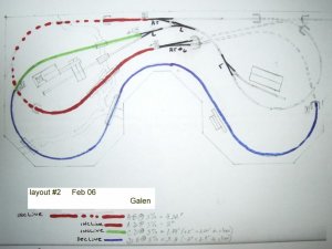
Okay here 'tis 2

http://www.trainweb.org/coalhauler/nazgul2a.JPG

A couple notes:

1. Grades - I managed to keep them at 3%. Not ideal, but not bad and WS makes 'em. This gives you an elevation of 4" at B, starting at A. The grade from C to D is necessary to clear the track on grade beneath it. Then from D down to E is one long grade.

2. Operations. Here's where it can be really fun. A morning passenger train leaves the station in the yard and heads through the tunnel, up the grade to B then around the loop to C. An intermediate station up here somewhere would be nice. Then up and over the hill from C to D and down to the small station before ducking into the tunnel at E and laying over there.

Meanwhile, the freight has been pumping up the brakes in the yard and has headed out. Arriving at B the freight switches the industry on the short siding. Perhaps an additional track can be added somewhere here. Anyway, as the freight finishes its work the passenger comes out of hiding and heads up the hill. The freight heads downhill into hiding at the tunnel E.

While the passenger train takes the cutoff at B and reverses direction, your shay or climax has coupled onto a caboose from the hack track and is 'gearing up' to leave. Ha. As the passenger arrives back in town the little engine heads up the line to serve the mine at C. This can be an out and back job, right back down the way it came up. It may have to hole up in the siding at the mine, however, as the freight heads uphill to take the reverse loop and head home to the yard.

While someone works the mine the freight arrives and is broken down. The engine heads off to the turntable for servicing in the shop and the little shifter comes out to put the caboose away next to the yard office (at the end of the yard track closest to the aisle), and work the industries. The long warehouse has two or three doors that require specific spots.

The mine run heads home and arrives just as the passenger train is ready for the afternoon run. And so on, and so forth.

Of course, DCC would make all this much easier. Micro Mark has got a great deal on the prodigy express system and MRC makes a reversing unit as well.

3. Scenery - I sketched in a creek tumbling down the mountainside and flowing into a stream below. There are areas where other structures can be added. The mine could be a pair of smaller industries, or put the siding on the other side of the grade (C-D) and run it into a dummy tunnel then use it as an interchange track - that universal industry. An additional spur next to the warehouse could act as the other interchange track, or just another yard track.

I'd put an access hole beneath the mountain to access the track from E to A and the 'yard lead'. Also a hole in the fascia on the far left would work to access the hidden track there. Again, those Woodland Scenics risers look pretty neat and I've heard great things about them. Setting the whole thing on two inches of pink foam would give room for the stream and any other ditches, culverts, etc. I chose 3% to allow for 4" clearance since the tracks cross each other 4 times. A piece of 1/4" ply or masonite will work for a 'bridge track', just nock out the grade risers and fit it in place. See the MR articles on building the wild west layout they did a couple years back...I think this is covered there.

Some sort of forest or non-attention-getting feature between the upper loop and yard area would be good to keep the distance (or lack thereof) from being so apparant.

All curves are 18" radius except the curve at D which is 20", just for fun and because it's the first thing folks will see coming into the room, if memory serves me right from your pictures. Not much difference, but a little.

Okay...plenty to digest. I may not have internet access Tuesday thru Friday so I may not be able to comment until Friday night or Saturday, we'll see. Have fun - it was alot of fun to sketch and plan (and dream).

Galen
 

ocalicreek

Member
May 4, 2005
824
0
16
48
Puyallup, WA
groups.yahoo.com
and another thing...

Oh yeah, the turnout at A is a #6 to allow for a better speed through there on the main loop. All others are #4's.

The innermost yard track is 18" rad, while the other two are 20" and 22" accordingly. The 2" spacing may be tight, you'll just have to play around with some flex track and see what works. Also, the crossovers at the end of the yard tracks may be a bit close, but with some minor modifications as suggested in another post it may work. There's a little wiggle room incase the track spacing needs to be wider.

Galen
 

Nazgul

Active Member
Jan 22, 2006
992
0
36
63
Ohio
Galen, you've really outdone yourself. I can't believe the work and imagination that went into this beautiful layout! You were right when you said that it was a lot to take in. The way you described the operations really made it come alive. Right off the bat, my only reservation would be...am I capable of doing this? I'm reading everything I can get my hands on (track work, wiring, dcc, ect.). I'm willing to take it one step at a time and make sure it's right (patience is one virtue I have in abundance).Thank you on behalf of my boys and of course myself. I'm sure I'll be talking to you.
 

Nazgul

Active Member
Jan 22, 2006
992
0
36
63
Ohio
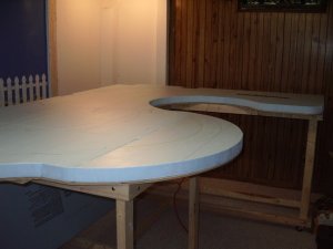
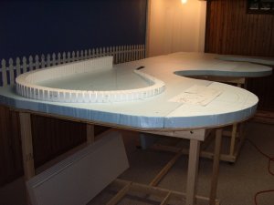
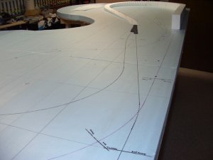
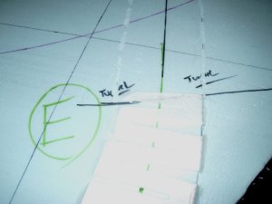
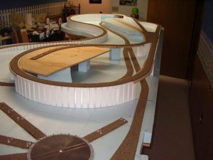
First of all, sorry for the poor lighting on the pictures. The 2" foam is down obviously and I have drawn the layout on the bench top. Started pinning down the W.S inclines to see how they are going to look. The first thing I did, after the foam, was to put a 1'-0 grid pattern on it to match the one I penciled in on Galen's plan. I have to admit, I can't believe how precise the plan is. I just tried to place everything as close to their relative positions on the drawing as I could. With a little trial and a whole lot of error, it came together. I test fitted every thing and it is all very smooth and flowing, no forcing or trying to fit things where they can't. If I have learned anything here on THE GAUGE it is.....any mistakes or poor judgement calls during this part of the process will haunt you for the life of your layout or until you rip out the problem areas....no thanks. I'll try to post when more progress is made or I need advise. Thank you everyone

Picture 019.jpg

Picture 020.jpg

Picture 021.jpg
 

ocalicreek

Member
May 4, 2005
824
0
16
48
Puyallup, WA
groups.yahoo.com
Wow, wow, WOW! That's great! Looks like you used a different color for the elevated sections? (or did you just run out of ink?)

Steve, I have real confidence that you'll be able to pull this off with flying colors. Your enthusiasm and energy for this project is high and your resolve seems strong.

It's pretty neat to see someone building one of my plans...kinda scary, like model railroad voyeurism of a sort. Vicarious modeling, maybe? Anyway...

Just a note: I generally allow for 3" between track center line and the edge. Personally, I think it gives you more room for scenery and makes photography a little easier. Practically, it can be a buffer zone if a long train topples over on its side. Better on its side on the layout than over the edge onto the floor. So when you reach the track laying stage take extra care test running trains. And, if you have got the aisle space, consider rolling the scenery over the edge, like rock outcrops and such. It'll give you more room for scenery, widen that buffer zone and it's a cool alternative to the typical masonite fascia.

Keep us posted, and keep up the great work. I'm glad you're having fun!

Galen
 

Nazgul

Active Member
Jan 22, 2006
992
0
36
63
Ohio
Galen, Thank you for the kind words. To answer your question about the diffent colored lines for different elevations...You have a good eye, that's exactly what I did ( as photo 1 shows). I did it to keep the layout "clear" in my mind and it seemed to work well. Only in one place am I closer than 3" to the edge (photo 2) and I have 2" there and I'll build up the edge to keep trains on the table. I have to purchase the turn-table so I can complete laying out the yard section. QUESTION: does anyone see a real problem with getting ATLAS turnouts ( they're pretty much all my LHS stocks)? I'll be powering them somehow, probably tortise....Man do I have a lot of things to buy yet, ouch!!!
I'll be talkin to you

Layout 001.jpg

Layout 004.jpg

Layout 005.jpg

Layout 006.jpg
 

ocalicreek

Member
May 4, 2005
824
0
16
48
Puyallup, WA
groups.yahoo.com
decline grade

Steve,

Did you use 3% for the decline grade? Maybe I calculated incorrectly but I had planned on it reaching the bottom of the grade before ducking beneath the upper loop. It shouldn't be a problem however, if the clearance is there.

As far as Atlas turnouts...I have used them in the past with good results. They may require some 'tuning' (a bit of careful filing in some places) but that's been covered well in the modeling mags 'getting started' type articles and I've never met a turnout that didn't need it. Well, maybe except my hand laid track...ha ha.

Again, looking great! Thanks for sharing photos & progress!

Galen
 

Nazgul

Active Member
Jan 22, 2006
992
0
36
63
Ohio
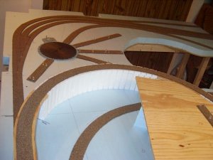
Galen, I thought I went too high at D and that was the problem. I didn't think It was a big deal so I didn't think any more about it until you brought up the clearance issue. After checking the clearance(it was the 3"min) I rechecked all heights and they were correct, as were your calculations. So what was the problem...I used stacked 3/4" risers and incline starters for the bottom 1/3 of the decline. Instead of using an incline starter which is 3/4" at one end, I mistakenly used a 3/4 riser which of course gave me a 2'-0 level section and extended the decline by 2'-0. Anyway, it didn't take long to fix and as you can see from the pictures, your calculations were spot on! Arizona Heat, the foam is 2". As far as copying it, if you read the rest of this thread you will see that it is ocalicreek's (Galen's) design. I'm sure there is no problem...It just can't come out better than mine!!!:D
 

Nazgul

Active Member
Jan 22, 2006
992
0
36
63
Ohio
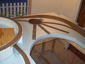
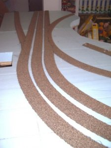
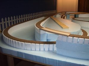
Here's what I've been doing since the last post. The roadbed is pretty much done and now I'm trying to decide on DCC systems. I'm really torn between saving money and going with the Podigy Express or going for the Zephyr. I'll pick one tomorrow and get on with it. Any way, I'm having a great time building the layout. When I started I thought I would really enjoy running trains the best but I'm having a blast making everything. This is the GREATEST HOBBY!

Layout 015.jpg

Layout 013.jpg

Layout 012.jpg

Layout 014.jpg

Layout 011.jpg
 

ocalicreek

Member
May 4, 2005
824
0
16
48
Puyallup, WA
groups.yahoo.com
Yes Yes Yes!!!

You've got it! Model Railroading IS fun!!!

Thank you for sharing the progress, but more importantly your enthusiasm. Just be careful...too much more excitement and folks may actually get out of their armchairs and start modeling!

Okay, so I'm looking at the pictures...seeing that last one is making me rethink putting a tunnel there on the plan. Of course it's your creation, but part of being on a list like this is putting up with the great creative suggestions you get from the rest of us. Seeing the curves cross over there, perhaps a short tunnel beneath the highpoint (D) would be best to leave that curve up the back grade exposed. Something like the tunnel beneath Tehachapi Loop (#9, I think) or similar.

So what are you thinking, scenically? Do you have a locale in mind? I wasn't thinking of any specific locale when drawing the plan, but the desert West, like Nevada gold country kept coming to mind. Ever been on the V&T out of Virginia City? Like I said, the choice is yours entirely.

And as for DCC, well, I bought the Prodigy Express system from Micro Mark back after Xmas but have yet to set it up and test it. That's due to my own procrastination, not the product itself. However, the decision to purchase this system was made after much research and cost was a BIG factor.

(On a personal note I am looking forward to wiring up the MDC Critter I just finished detailing recently and giving it a go. Plus the Mantua Shifter superdetail project I've been working on occasionally is about to get a good shot in the arm as the can motor repower kits are in at YardBird Trains and one is in the mail to me as I write this! So it's going to get a decoder as well and will be run on my switching module with the MRC steam synchro sound system. That should be fun...)

Thanks again for sharing the progress. It's a real thrill to see the plan I sketched all fleshed out like this. My own layout plans had been stalled for a time but your progress is spurring me on to work again.:thumb:

Galen
 

Nazgul

Active Member
Jan 22, 2006
992
0
36
63
Ohio
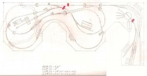
Thank you G E C I'm tryin to do the best Job I can...Galen, I was thinking the same thing about the top track at D. As far as the locale, I like the looks of the layout at pacificcoastairlinerr.com, It's use of rocks,cliffs,and water really would look great on this layout but I really haven't deciced for sure. Now I have a question...I'm quickly comming to the part of this project that I am completely in the dark about, WIRING! I posted a picture of where I think I have to gap the track with plastic rail joiners, at the reverse loop on top and the turntable. Am I missing something? I know I should isolate the layout into blocks to make trouble shooting problems easier. Can I get suggestions on possibilities and or necessities? I'm lost when it comes to electricity/electronics...Thanks in advance, back to my wiring books zzzzzzzz

nazgul2a-insulated-gaps.jpg