Clayton Point light tower....

shaygetz

Active Member
May 2, 2003
3,612
0
36
64
www.freewebs.com
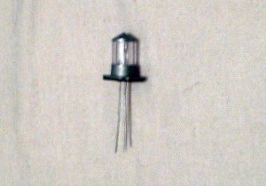
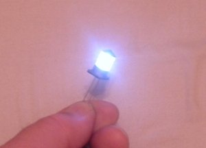
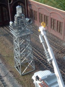
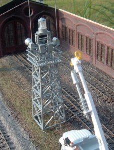
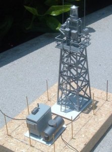
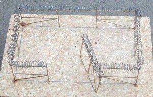
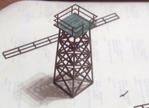
Thought I'd make my photo contest entry a small diorama centering around an inlet to an inland bay with a small stretch of beach to one side. With that I purchased a "firefly" circuit kit that I will use to light the unmanned modern light tower.

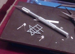
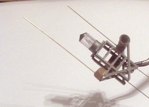
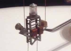
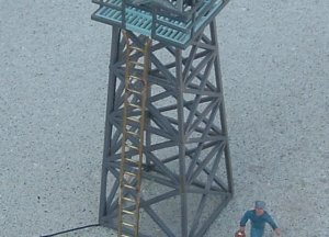
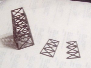
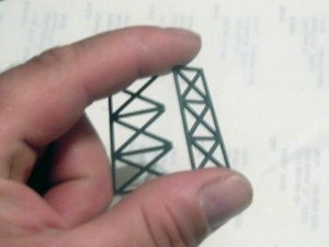
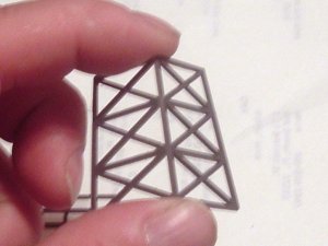
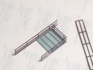
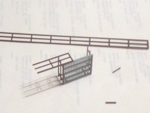
Starting with the remnants of a Volmer N scale pedestrian overpass, I cut the vertical legs off of one side to reduce the bulkiness of the final iron work. I then glued them together at the webs. It is surprizingly strong.
 

Attachments

  • clayton1.jpg
    clayton1.jpg
    43.5 KB · Views: 531
  • clayton1a.jpg
    clayton1a.jpg
    43 KB · Views: 530
  • clayton3.jpg
    clayton3.jpg
    45.5 KB · Views: 530

shaygetz

Active Member
May 2, 2003
3,612
0
36
64
www.freewebs.com
Because I wanted the tower to be airy, I used some scrap fire escape parts to make the light tower's floor. I simply sanded the two parts evenly so that, when joined, it would look as one piece. I then ringed it with Plast-struct railing. The two sub-assemblies are shown together, but are not glued just yet.
 

Attachments

  • clayton4.jpg
    clayton4.jpg
    44.7 KB · Views: 524
  • clayton5.jpg
    clayton5.jpg
    39.1 KB · Views: 517
  • clayton6.jpg
    clayton6.jpg
    49.2 KB · Views: 513

shaygetz

Active Member
May 2, 2003
3,612
0
36
64
www.freewebs.com
Thanks, guys.

Started on the light and antenna rack tonight, using a castoff part from a power station as a base. Using bi-color LEDs to represent channel markers, I filed them flat on the back and top, then fashioned a housing around them from styrene sheet. Once mounted, they will be wired in using brass wire stock shaped to appear like conduit. I used bi-color LEDs for two reasons. Asthetically, they are more realistic looking then those with colored lenses. Practically, once wired properly, no matter which side the channel winds up on in the finished scene, my colors can be properly oriented simply by reversing the polarity of the power---red for the shoal side, green for the channel. Much too delicate a project to have a :rolleyes: "Duh":rolleyes: moment on late in the game:thumb:
 

Attachments

  • claytona.jpg
    claytona.jpg
    52.5 KB · Views: 455

shaygetz

Active Member
May 2, 2003
3,612
0
36
64
www.freewebs.com
The light itself is now ready...and working. It is a combination of an old smokestack base, a chimney cap and a section off of an old pen.
 

Attachments

  • clayton7.jpg
    clayton7.jpg
    57.3 KB · Views: 430
  • clayton8.jpg
    clayton8.jpg
    33.5 KB · Views: 428

shaygetz

Active Member
May 2, 2003
3,612
0
36
64
www.freewebs.com
Today found me dropping the channel markers as the prototype I have in mind did not have them as I first thought. Anyhow, the upper tower is finished and shows the fog horn (a reshaped kibble as are both radio boxes) and its radio box and antennae. Electrical junction boxes came from Atlas telephone pole kits. Also shown is the radio box and antennae of the light itself---who uses people anymore:rolleyes:

The final shot shows it all together, lacking only the ladder for maintenance access. Note the wiring for the light, a 3mm LED that I had in the scrapbox. Testing is constant as the wiring and joints are as fine as I dare.
 

Attachments

  • clayton9.jpg
    clayton9.jpg
    43.8 KB · Views: 410
  • clayton10.jpg
    clayton10.jpg
    43.7 KB · Views: 405
  • clayton11.jpg
    clayton11.jpg
    28.3 KB · Views: 419

shaygetz

Active Member
May 2, 2003
3,612
0
36
64
www.freewebs.com
MilesWestern said:
jawdrop That's beautiful, and stunning piece of engineering, Shaygetz!!! :thumb: DO you plan to have a loop recording of a foghorn playing?

Thank you, Miles...yes, I do plan to have a taped fog horn playing thru a speaker imbedded into the rocks of the getty it sits on.

The brass ladder is now on with four soldered stand offs for durability.

I've changed the original pics for ones done in a better light to better show the details.
 

Attachments

  • clayton15.jpg
    clayton15.jpg
    36.6 KB · Views: 400
  • clayton16.jpg
    clayton16.jpg
    44.4 KB · Views: 399
  • clayton17.jpg
    clayton17.jpg
    61.4 KB · Views: 387
  • clayton18.jpg
    clayton18.jpg
    62.1 KB · Views: 386
  • clayton14.jpg
    clayton14.jpg
    56.2 KB · Views: 380

Russ Bellinis

Active Member
Feb 13, 2003
4,501
0
36
78
Lakewood, Ca.
Visit site
I noticed you mentioned bipolar leds to allow a red one on one side and green one on the other side. Are you making more than one tower? Generally a light o to warn ships away from rocks would be a clear rotating beacon. Red and green were used as channel markers. The rule that every seaman memorises is red-right-returning. Channel markers are always placed so that the green lights are on the right side and red lights to the left when going out of the channel. When coming back in, the red markers are kept to the right and green to the left. You would never have a red and green light on the same marker whether a bouy or a light tower. If they did that it would be marking the channel as going directly through the center of the tower.
 

shaygetz

Active Member
May 2, 2003
3,612
0
36
64
www.freewebs.com
Russ Bellinis said:
I noticed you mentioned bipolar leds to allow a red one on one side and green one on the other side.

To be honest, Russ, I don't quite know what I was thinking... I grew up near the prototype as a child and always seemed to remember some kind of setup like I was imagining, only to find my memories betraying me.:rolleyes: They will make a dandy addition to my harbor tug though:thumb:
 

shaygetz

Active Member
May 2, 2003
3,612
0
36
64
www.freewebs.com
The paint is now on and ready for the rest of the scene...a chain link fence and generator. The scariest part for any project for me is the paint---I always fear messing up. With its fine ironwork this one was no exception but I was pleased with the results. The prototype is regularly painted and well maintained but silver is way too shiny on models. I sprayed it with silver paint first then followed it with Dulcote. It makes for a nice aged silver paint/ galvanized look.
 

Attachments

  • claytonb2.jpg
    claytonb2.jpg
    62.8 KB · Views: 363
  • claytonc1.jpg
    claytonc1.jpg
    63.1 KB · Views: 358
  • claytond.jpg
    claytond.jpg
    62.8 KB · Views: 346
  • claytone.jpg
    claytone.jpg
    60.5 KB · Views: 346

jim currie

Active Member
Jun 29, 2003
1,383
0
36
arizona
Visit site
great job Bob for a referance Testors make a color called steel not near as glossy looking as silver.:) and brushed on it gives a real nice look of zink platind.
 

shaygetz

Active Member
May 2, 2003
3,612
0
36
64
www.freewebs.com
jim currie said:
great job Bob for a referance Testors make a color called steel not near as glossy looking as silver.:) and brushed on it gives a real nice look of zink platind.

Thanks, Jim...as for the paint, I haven't seen it around here in a while. I usually do it with a homemade concoction---1 part flat black to 4 parts silver, but I'm really warming up to this new way I've tryed. I'm really pleased with the effect.

The plot of ground now set, I've "poured" the concrete pads for the tower and generator. The wire will go thru holes drilled in the block. The generator and tank were a clearance A-Line kit in the dust bin of a local hobby shop. I've also started the fence per my water tower project

>>>http://www.the-gauge.com/showthread.php?t=10813.

This time, because it is in such a remote location, I'm going to try a technique for modeling coiled razor wire I've been playing with. Gotta keep those delinquent LPBs at bay.:thumb:
 

Attachments

  • clayton18.jpg
    clayton18.jpg
    54.7 KB · Views: 170
  • clayton19.jpg
    clayton19.jpg
    49.9 KB · Views: 169

doctorwayne

Active Member
Sep 6, 2005
3,516
0
36
Canada, eh?
Excellent work, Bob, and what a neat (and seldom-modelled) prototype. And in my opinion, your painting skills are on a par with your scratchbuilding talents. Well done.

Wayne
 

zedob

Member
Dec 26, 2004
757
0
16
62
Chicopee, MA
That's a great job on a really cool project. The lens of the light even has that fresnel look. I used to make some parts for lights like that for a NAV-AID company in Louisiana and the light is a very close representation of the real thing. The assortment of control and battery boxes looks about right too.
 

shaygetz

Active Member
May 2, 2003
3,612
0
36
64
www.freewebs.com
Thank you, Wayne.

Appreciate your input, Z, as this is meant to represent them and not be a model of a particular light tower hence, the Mostly Credible part of the Basic and Mostly Credible Railroad. When I noticed the fresnel effect on the pen barrel, I couldn't resist and it really does work...the little booger is intensely bright. The only place I took real liberty without prototype verification is the generator. I had one and it just seemed like a practical place to put it, especially when one lives in hurricane country like I do. I would suspect that, like the sewage lift stations around here, that they would have connections available for a large portable generator to hook up to.

The fence posts are dug and the frame work is up. I added blocks to the base to provide room for the firefly circuit to be installed. Ever reminded of how well brass wire conducts heat at this point in a project, too...:eek:ops:
 

Attachments

  • clayton20.jpg
    clayton20.jpg
    57.1 KB · Views: 156

shaygetz

Active Member
May 2, 2003
3,612
0
36
64
www.freewebs.com
The razor wire top went in today. I coiled the wire on the straight end of a good paintbrush into 18" coils. Then I applied it to the top of the fence by soaking it in Crazy Glue, the liquid kind, as I slowly pulled it off of the brush.
 

Attachments

  • clayton21.jpg
    clayton21.jpg
    43.9 KB · Views: 156
  • clayton22.jpg
    clayton22.jpg
    50.8 KB · Views: 152
  • clayton23.jpg
    clayton23.jpg
    66.4 KB · Views: 154