Catenary Clinic

Chris (interurban) and I have been discussing catenary design on and off now for what? A year now, Chris? Seems like it, anyway. When it comes to catenary design, there is a complete lack of information for the modeler. This is not the same as trolley overhead. Catenary is used for heavy traction equipment and is still in use today in some parts of the country, notably along the old South Shore Line and the Northeast Corridor. It's difficult to really understand the purpose of the maze of wires, hangers, and insulators, especially when there are towers, messenger wires, tie-back or pull-back cables, designs just for curves, etc. And, to make it even MORE complicated, there were different design types, too. Here in Connecticut, for example, I can study the NYNH&H RR's original 'triangular' catenary with 'flying hangers'. I've had my face in Don Ball's great book on the Pennsylvania RR looking at photos of catenary getting ideas from there. The PRR and DL&W catenary is both similar in design and both differ from that of the New Haven RR! I intend on designing and building my own catenary for my layout and NOT to power my locos. It will be unpowered and will be as close to prototypical as possible. In order to do this, I'm going to design and build two towers with catenary suspended between them over a double track mainline as a diorama. As I begin, I'll design the hanging system complete with insulators, tranmission lines, hangers, etc. I'll scratchbuild the towers, suspension lines between the tower legs, and hangers. For the actual catenary, I'll use the Model Memories pre-fab catenary. This will take a bit of time, but I'll supply the plans and progress photos as I go along. Of course, I welcome all suggestions and input from other traction modelers! :thumb:

Russ
 
N Gauger said:
If you need any Piccys - Of "Details" Let me know - I guess I could be "Forced" into going the 3 blocks to the railroad.. :) One more time" :) :) :) That's how far I'm from "The NE corridor"

Thanks, Mike! The catenary here is getting updated with new hangers and that's giving it a different look. Also, people are pretty trigger-happy when it comes to railfans and cameras. I can visually check out the cat along the ROW here in CT between New Haven and Stamford up close in places. One great spot is right behind a Dairy Queen in Fairfield! :D Photos of insulated hangers, towers, etc. would be gratly appreciated. My design will follow the DL&W/PRR prototype. May have to take a field trip to the ol' DL&W ROW in NJ, too. Shucks...more railfanning! :thumb:
 
Basic PRR Catenary

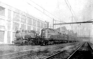
To introduce catenary design, I've scanned a photo from Edwin Alexander's book 'The Pennsylvania Railroad, A Pictorial History', now long out of print. Here's the link to the photo:

http://img.villagephotos.com/p/2004-7/788680/PRRCat1001.jpg

If you notice, the PRR used simple steel I-beam towers to suspend the catenary, even over a 4-track main as in the photo! For modeling purposes, I'm going to follow the same construction pattern. This is also similar to the DL&W catenary, as can be seen in this postcard view from my collection. Here's the link:

http://img.villagephotos.com/p/2004-7/788680/DLWCat1.jpg

One major difference here is in the way the messenger and trolley wire are suspended. In the PRR design, the catenary is suspended from a system consisting of 'cross catenary' and 'body spans'. In the DL&W construction in the postcard view, the cross catenary and body span has been replaced with a steel beam connecting the two tower beams. The power transmission lines, however, still run from tower top to tower top. In the PRR design, the transmission lines are suspended from long insulators; the DL&W used small cross-arms attached to a mast mounted to the top of the tower I-beams.
The PRR system in the photo is not a design used by that railroad everywhere because this design requires a good deal of open space along the right-of-way. Space restrictions dictate the type of tower that can be used. Simple high I-beam towers were steadied with guy wires anchored into the ROW to cross large, open expanses of land. In more developed areas where overpasses and buildings along the ROW restricted transmission tower height and ROW width, heavier I-beam towers with the cross I-beam to suspend the catenary was used. This is evident in the lower height profile of the DL&W construction as it passed through urban and congested suburban areas. As always, there are no hard, fast rules. You'll see cross-catenary suspension wires used in tight yard areas (steel cable is cheaper than steel I-beams) and steel cross-catenary beams used in tight station and teminal areas. The catenary has to be stable and not wave, although there is some waving action along the length of the line as high speed trains with pantographs press up against the contact wire. The stress from such use also played a key role in how the towers and catenary was suspended. In a yard area where traffic is slower, the stability factor is less critical. Towers can be of a less complicated arrangement and not be held back with guy wires to keep the tall towers straight and tightly spaced apart because of the lower speeds and traffic density.
For my layout, I'll have my catenary suspended from cross-catenary beam suspension on the main and cross-catenary wire suspension in the yards. More to follow! :wave:
 

60103

Pooh Bah
Mar 25, 2002
4,754
0
36
Brampton, Ontario, Canada
Visit site
Russ:
I mentioned in my post on Enola yard, there are still towers and cross catenary there. I think the towers were laced beams, but then we didn't stop.
Also some solid I beams with beams over the tracks.
You could get some good pics of the cross catenary without the rest of the wires confusing the issue.
 

green_elite_cab

Keep It Moving!
Apr 4, 2005
1,876
0
36
34
Hainesport NJ
hooray!

someone else is trying the same stuff i am! i already started the catenary wires though, but only the trolley wire and auxilary wire. amazingly i got the steal music wire to solder withoug a problem once i put some flux on it.

because other than the cork road bed, and a few buildings, i have no scnerey, and nothing is mounted down yet, so i'm to put up my catenary poles until the scenre along the track is done

chris (seperate chris)
 

Gary Pfeil

Active Member
May 7, 2001
2,510
0
36
Boonton NJ
Visit site
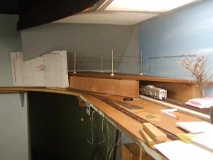
Hey HudsonElectric, and all others, I just was directed to this thread from a search I did for Pennsy catenary info. Funny, right here on the Gauge, my home! Anyway, while I am not modeling electrified operations, I have decided to use a stretch of northeast corridor to conceal my freelanced lines main as it goes thru a wall into staging in an adjacent room. Here is a photo of early stage design process. My main concern right now is how to make where the four tracks and overhead wires meet the backdrop on the right side. The white cardboard, and the area beyond the corridor, will be brick buildings, and they will serve to disguise the tracks running into the wall at left, from most angles. The right side is more difficult. The line I've drawn on the backdrop represents teh crossbeam of a catenary bridge as it would need to be painted where the wires would hot the backdrop. The sharp angle makes this pretty difficult. The photo will follow on my next post as I've typed this on the quick reply!

Gary
 

Gary Pfeil

Active Member
May 7, 2001
2,510
0
36
Boonton NJ
Visit site
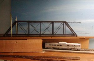
After pondering how to make the best of a difficult situation, a friend mentioned that if I used a truss ridge to span the JGL tracks, the busyness of the bridge components would lead the eye away from the backdrop. I have a Central Valley truss bridge I built as designed and I took the superstructure and laid it on the trackboard to see hopw it would look. The bridge is too long, I would need to build it with one section removed, and skewed. But I think it could work out well. Here is a photo of it sitting there. Use your imagination! Bear in mind when built skewed, it would be slid to the right quite a bit.
 

Attachments

  • necor9.jpg
    necor9.jpg
    57 KB · Views: 215

Gary Pfeil

Active Member
May 7, 2001
2,510
0
36
Boonton NJ
Visit site
So now for my big question, is there any truss style bridges on any sections of electrified track? And if so, how would the catenary be handled passing thru them? Any links to photos would be appreciated, as well as any comments/suggestions on what I'm planning to do.

Thanks, Gary
 

green_elite_cab

Keep It Moving!
Apr 4, 2005
1,876
0
36
34
Hainesport NJ
Gary H Pfeil said:
So now for my big question, is there any truss style bridges on any sections of electrified track? And if so, how would the catenary be handled passing thru them? Any links to photos would be appreciated, as well as any comments/suggestions on what I'm planning to do.

Thanks, Gary

there are no truss bridges like that that i am aware of except for the bronx kill span of the Hell Gate Bridge in New York city. it seems like your bridge only crosses tracks, so you really only need a regular girder bridge, its not really realistic to use that truss bridge. chances are you would have to scratch build some sort of thing to hold the catenary in the bridge, and make the transmission towers ( if you decided to add them because they are everywhere on the NEC it will make it mroe realistic) higher if you use that bridge.

it will be more realistic to install a plate girder bridge, with normal catenary ( including transmission lines) and much easier.

btw, are those the model memories kits, or did you scratch build your catenary? i'm scratchbuilding mine, but i don't know when i will be able to put it all up. i'm doing NJT north jeresey coastline in south amboy.
 

green_elite_cab

Keep It Moving!
Apr 4, 2005
1,876
0
36
34
Hainesport NJ
i suggest you get 2 of these. this will be much more realistic and easier for you to do. they are Micro Engineering's 100' Double Track Thru Girder Bridge.

internettrains_1871_541090336


the Catenary wire will just go straight over it, no fuss. after all thats the idea of the prototype. nice and accessible.

putting the 2 of those bridges together looks alot like the ones i see in metuchen, NJ when i visit my family.

here is an example ( although scene from space) of what i'm talking about. since your tracks are only a short span to go oever, you get 4 individual spans for each track going over your freelanced mainline the tracks to the left are the NEC, and the 2 to the right are going into a freight yard. still, they work.
necbridge8av.jpg
 

Gary Pfeil

Active Member
May 7, 2001
2,510
0
36
Boonton NJ
Visit site
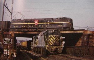
Thanks Chris, and Chris, Here is a shot from a CNJ book showing the inspiration for this scene, I had intended to build as shown. My first photo shows the deck, the edges of the plywood would become concrete and I will cast cut stone walls over the 2x4. However, as I said where the wires meet the wall is a bit of a dilema. The truss bridge does solve that, at the expense, apparently, of not being prototypical. I appreciate your suggestion of girder bridges, I understand they would be correct. But they don't help hide the wall so if I don't use the truss, I'll probably go with the concrete as in the photo. While I like to follow prototype, I will veer from it in order to solve a problem such as this. I'm still not sure which way I'm going to go. I don't mind the work involved to route the wiring thru the bridge, but would really like to see how it is handled, if not on a similar bridge, then at least in some other somewhat similar situation, like a low clearance perhaps.

Yes, those bridges are by Model Memories. I had seen an article on using brazing rod and code 100 rail to build your own and was going to go that route when I found these existed, so I bought these instead.
 

Attachments

  • necor2.jpg
    necor2.jpg
    59.2 KB · Views: 72

green_elite_cab

Keep It Moving!
Apr 4, 2005
1,876
0
36
34
Hainesport NJ
wow that really is an impressive and inspirational picture. thats the kind of thing i wanted to do if i had the space, but whenever i planned a NEC layout, it turned monsterous. i'll have to wait until i have my own house.

would you happen to know what bridge that is, or where its at?

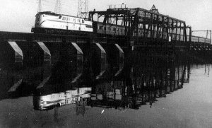
if you sincerely want to use a truss bride, there is a truss bridge that looks alot like the one in your photo ( except its silver or aluminum colored) but its in connecitcut going over some water.

there is a truss style bridge that goes over the susquehanna river that looks alot like walthers swing bridge

I have also seen that catenary article, and thats why i plan to do. i wish i could use the model memories stuff, but its just way to expensive for me. i'm able to make my own stuff at much cheaper prices ( although some of it is tedious, i already started makeing my own catenary wire, and sanding it smooth is annoying) at the same time. the brazing rods are round, and that isn't realistic. I haven't been able to find the right size structural shapes for it either,
 

Gary Pfeil

Active Member
May 7, 2001
2,510
0
36
Boonton NJ
Visit site
Chris (NJ Chris!) That photo is from Broad Street, Elizabeth. Now, on my railroad, that GG1 is about to hit a wall. I could take a photo from this angle, but if I move to the left and take a side shot of the CNJ GP35, those catenary wires either ending in midair or touching a painted on catenary bridge will be very obvious.

Chris, Thanks for that photo. I'm going to see if I can get it on my photo program and enlarge the area where wires enter the bridge structure to see how it is done. If you have access to a detail shot and don't mind searching for it, I would really appreciate it. I may get one double track truss bridge to build and if it goes well, get the other I'll need. This project just got to be a much longer job than originally planned!

Gary