building a turnout

t. alexander

Member
Jun 20, 2002
540
0
16
61
Attalla Al.
Visit site
Hi folks spent the afternoon building my first curved turnout.
I have a template I use for the straights but nothing to go by for the curved. Ended up just making a tracing using flex track to get the frog point and angle. This method should work well for me and it also means I can custom fit them to the situation. I'll be spiking this one down tommorrow.
 

Attachments

  • untitled-1.jpg
    untitled-1.jpg
    23.3 KB · Views: 354

t. alexander

Member
Jun 20, 2002
540
0
16
61
Attalla Al.
Visit site
As you can see I glued the switch ties full width and will trim them after the glue has dried

this next pic is the turnout being built over the tracing
 

Attachments

  • turnout.jpg
    turnout.jpg
    18.8 KB · Views: 322

kettlestack

Member
Jan 18, 2002
859
0
16
84
Scotland UK
Visit site
That's superb t. Handlaid track looks great, but it needs courage to go do it. My Hat's off to you, you couragous man! :)

Are you not fearfull the track will distort when you crop the ties?

Errol
 

shamus

Registered Member
Dec 17, 2000
3,489
0
36
87
UK
Nice work t, thats something I have never ever contemplated doing. I think that anyone who makes their own trackwork Deserve a medal. Well done.

Shamus
waver.gif


Gary Pfeil

Active Member
May 7, 2001
2,510
0
36
Boonton NJ
Visit site
Hi t, It looks great. I take it you are building on your workbench and then laying? In regard to the tie templates, I used to use them too, I stopped after my first 5 or 6 turnouts when my confidence level went up and I realized there was no reason to confine myself to #6, or 8 or 4 for that matter. There certainly is no relation to the prototype in those sizes. Trackplans call for them because they are commercially available.
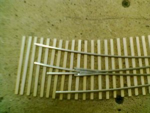
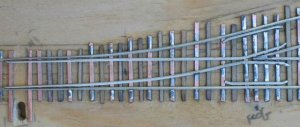
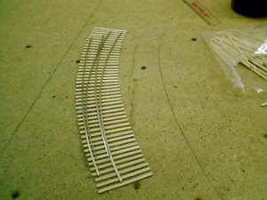
Now, I just layout the track centerlines, glue down the homabed (or cork, but homabed is better for spiking) on the centerlines then its time to glue ties to the homabed. I cut ties form commercially available switch ties. I cut them in 1' increments, 9 1/2, 10 1/2, so on. I built a jig to space the ties how I want them. Here is how I determine how many of each tie length to use, I developed this for curved turnouts. I use flextrack pinned down for one of the routes to mark where the tie ends will be, then do the same for the other route. Beyond the throwbar I usualy use 2 or 3 standard ties, then go to 9 1/2" ones. I simply see how far from the points the 9 1/2' tie matches the drawn lines, and put that many 9 1/2' ties in the jig, then do the same up to the full length switch ties, beyond which regular ties are used for each route. When all ties are in the jig, I use a thin strip of masking tape to move the strip into place on the homabed. Oh, before I forget, drill a hole under where the throwbar will be if you are using under table machine to throw the turnout before gluing the ties down. Once glued down, and sanded level, I paint the ties and homabed a suitable tie color. This seals the homabed to protect it from the water used in ballasting. There is presently another thread on coloring ties, and everybody else stains their ties. I used to also, but have decided to defy conventional wisdom, I feel it is easily possible to obtain the effects you want with paint. In addition to the paint sealing the homasote, which is important (and the ties adhere to the homabed with white glue very well prior to painting) I never liked having to seperate and turn ties after a stain bath. To each their own.
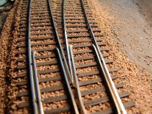
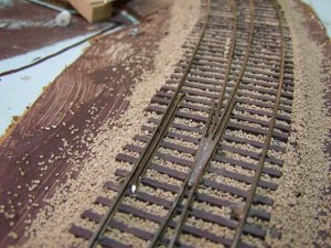
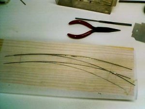
Next is ballasting. When this is dry and cleaned off tie tops, it is time to lay rail. No need to go into this, as you have done quite well! As long as the turnout in question is accesable on the layout, I prefer to build in place. Actually, I have never built one on my workbench.
I hope some part of this has been helpful.
 

t. alexander

Member
Jun 20, 2002
540
0
16
61
Attalla Al.
Visit site
Hi All
Shamus thank you, With your modeling talents I bet you could do it with one hand tied behind your back! Ah heck prolly both!!

Clerg The ties Im using are made by Micro Engineering. but when I run out of this bag I'll prolly cut my own from bass wood or cypress.

Gary Thanks for all the helpfull info I'll be painting these too I'd imaging to match what ever color the atlas flex ties turn out to be.
Hopefully my confidence level will rise enough to build them in place too. Your right I am building the frogs on the bench.
I am not sure how the turnouts will be thrown yet I do now it will be manual though, choke cable or something similar.

Cidchase I got as close as I could with my poor camera unfortunetly I don't think it will help. Mabey Gary can do you a close up frog shot. there is quit a bit of filing and fitting that goes into the frogs that can't be seen because the solder covers it.
As far as wiring They will be live frogs which means current will be running through the entire frog.

t.
 

Attachments

  • switchfrog.jpg
    switchfrog.jpg
    30 KB · Views: 281

Gary Pfeil

Active Member
May 7, 2001
2,510
0
36
Boonton NJ
Visit site
Tyson, the frog will need to be gapped. Best approach is to cut all four rails coming from the frog fairly close. The point rails should each have a feeder to the same buss as the stock rail adjacent to it. The diverging rails each get feeders to the appropriate buss wire as well. The frog is powered thru a switch which throws with the turnout. Or, the frog can be left dead. If it is very short it would then be the same as many commercial turnouts. All the more recent locos have all wheel pickup and would negotiate it fine. I however power all mine. All locos, even an 0-4-0 will creep thru them.

Gary
 

Gary Pfeil

Active Member
May 7, 2001
2,510
0
36
Boonton NJ
Visit site
I went downstairs and took a couple quick shots of frogs. First one hasn't yet been soldered, been in service over a year. I tend to move along and don't always finish the job!
 

Attachments

  • p1010177jpg.jpg
    p1010177jpg.jpg
    96.8 KB · Views: 260

Gary Pfeil

Active Member
May 7, 2001
2,510
0
36
Boonton NJ
Visit site
T, you can see what I was talking about concerning the ties in these photos as well. Templates? I don't need no stinkin templates! You don't either. it's a piece of cake.

Gary
 

jkristia

Member
Aug 1, 2002
426
0
16
56
Simi Valley, CA,
Visit site
Here is a picture of one of my code 40 n scale turnouts. I still need to cut a gap in all the pc ties and in the frog. Right now I'm ballasting the track with WS fine ballast. I will post some pictures when it's done and the ties and rail is weathered. I just ordered some Arizona & Rock ballast and will use that next time as I think it looks better (more true to scale) than WS.

Jesper
 

Attachments

  • img_2206.jpg
    img_2206.jpg
    35.5 KB · Views: 158

Gary Pfeil

Active Member
May 7, 2001
2,510
0
36
Boonton NJ
Visit site
Looks good Jesper. A question: You were the one asking about staining ties, here and on a couple other forums. I see you are soldering ( I haven't done so) due to the small size of the rail. How do you intend to get the pcb ties to match the stained wood ones?
 

jkristia

Member
Aug 1, 2002
426
0
16
56
Simi Valley, CA,
Visit site
Gary, I decided to go the easy way, paint it all after the rails are installed.

First I had planned to stain the ties, apply the ballast, install the rails and then give it all a light coat of grimy black with the airbrush, that’s the way I have been told they do it in San Diego – SDSons. But after doing a small test track I realized that it’s too difficult (or at least too much work) to clean the pc ties before soldering, so I think the way I will do it from now on is to paint it all tie-brown after the rails are installed and then maybe give it a grimy black coat with the airbrush.

Jesper