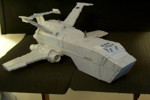
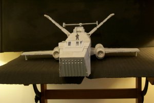
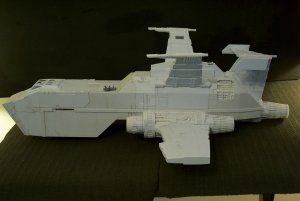
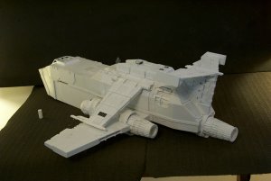
Blackadder's Scratchbuilt Thunderhawk Redux
- Thread starter Blackadder
- Start date
You are using an out of date browser. It may not display this or other websites correctly.
You should upgrade or use an alternative browser.
You should upgrade or use an alternative browser.
Thanks for the reply,
This is what Zathros was hinting at on the last page..........
Ball turrets:
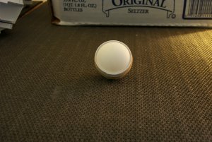
I'm out on a limb starting this with an image of table tennis balls but I am going to try to use these for a basis to model the turrets.

I want mine to open the same as the FW original:
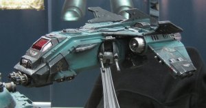
So we'll see together where this will lead.
The balls are 1.5 inches in diameter (39 MM). First does anyone know the diameter of the Raven Turret? Just curious is all because I think this is a good size for the T'hawk.........
Well I had to play 'Dad' and help my daughter to move into her new apartment today but before that a bit of work on the turret. I have confirmed by an unusually reliable source that the turret ball is slightly more than 1.5 inches 38,0 MM
in diameter precisely my estimation but nice to have verification.
Anyway wrapping the ball with 0.5 MM styrene gives me a gun race of 1.6 inches perfect for the Thunderhawk.
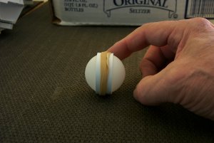
With the gum bands removed there appears a good start for this interesting modification.
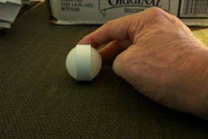
Ball Turrets Two:
Reinforced center axis installed, Rotation axle installed sides flattened to receive gun mount axles.
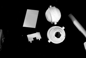
Previously I demonstrated and suggested an easy way to add detail to projects by utilizing scrap discs left over from drilling holes in styrene. That offering apparently fell on fallow ground other than to generate not a few replies that I "mistakenly" posted either triplicates or on the wrong thread entirely; Ha! I just felt that the information applied equally to all my scratch projects.
That intentional ''blanket'' suggestion was a precursor to the current project where I am attempting to recreate the FW "Ball Turret" for my Thunderhawk.
Making the turret operable may have been a bit too ambitious at least for the way I conceptualized the assembly.
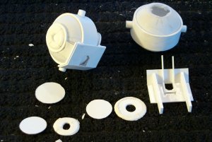
(BTW I am not aware whether the FW Ball Turret functions on all three operational (axēs) parameters?)
Anyway employing the scrap discs to supply two of the three axēs I needed now only address the rotational axle.
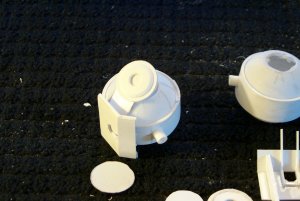
I'm sorry to say I'm not at all pleased with the overall result which appears to me too cumbersome.
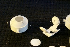
Especially the straps that append the training axle to the targeting race.
This is what Zathros was hinting at on the last page..........
Ball turrets:
I'm out on a limb starting this with an image of table tennis balls but I am going to try to use these for a basis to model the turrets.

I want mine to open the same as the FW original:

So we'll see together where this will lead.
The balls are 1.5 inches in diameter (39 MM). First does anyone know the diameter of the Raven Turret? Just curious is all because I think this is a good size for the T'hawk.........
Well I had to play 'Dad' and help my daughter to move into her new apartment today but before that a bit of work on the turret. I have confirmed by an unusually reliable source that the turret ball is slightly more than 1.5 inches 38,0 MM
in diameter precisely my estimation but nice to have verification.
Anyway wrapping the ball with 0.5 MM styrene gives me a gun race of 1.6 inches perfect for the Thunderhawk.


With the gum bands removed there appears a good start for this interesting modification.

Ball Turrets Two:
Reinforced center axis installed, Rotation axle installed sides flattened to receive gun mount axles.

Previously I demonstrated and suggested an easy way to add detail to projects by utilizing scrap discs left over from drilling holes in styrene. That offering apparently fell on fallow ground other than to generate not a few replies that I "mistakenly" posted either triplicates or on the wrong thread entirely; Ha! I just felt that the information applied equally to all my scratch projects.
That intentional ''blanket'' suggestion was a precursor to the current project where I am attempting to recreate the FW "Ball Turret" for my Thunderhawk.
Making the turret operable may have been a bit too ambitious at least for the way I conceptualized the assembly.

(BTW I am not aware whether the FW Ball Turret functions on all three operational (axēs) parameters?)
Anyway employing the scrap discs to supply two of the three axēs I needed now only address the rotational axle.

I'm sorry to say I'm not at all pleased with the overall result which appears to me too cumbersome.

Especially the straps that append the training axle to the targeting race.
Foam Core! The Bane Of My Existence:
Once again I have come to regret the folly of using foam core poster board for a quick and easy and inexpensive way to frame a model.
It's alright for some; rational people secure in their competence that they will not change that which is satisfactory. But for a neurotic like me who is dissatisfied with completion and goes to extraordinary lengths to forestall that eventuality foam is a bad way to go.
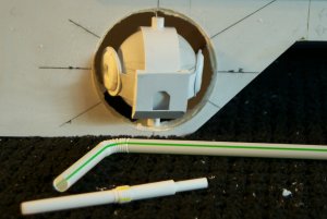
Here we see the first inroads into cutting a socket fo the future ball mount. The yellowed area is resin applied to foam board to secure the styrene skin to the poster board frame.
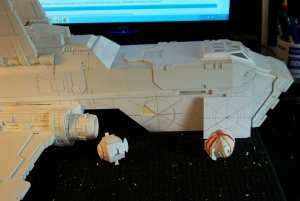
So what time have I saved when I have now to build the cargo bay inside out now to install the ball turret module.
The left side with the ball temporary mounted in the cutout for scale.
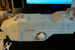
There seems ample room for the entire module and a fairly uncluttered field of fire for this weapon with 'interrupters' installed to prevent shooting off the still to be fabricated canards and the wings and the engines.
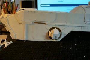
A closeup of the accordion boot fabricate from a bendable soda straw for the recoil-less AA gun barrel.
Once again I have come to regret the folly of using foam core poster board for a quick and easy and inexpensive way to frame a model.
It's alright for some; rational people secure in their competence that they will not change that which is satisfactory. But for a neurotic like me who is dissatisfied with completion and goes to extraordinary lengths to forestall that eventuality foam is a bad way to go.
Here we see the first inroads into cutting a socket fo the future ball mount. The yellowed area is resin applied to foam board to secure the styrene skin to the poster board frame.

So what time have I saved when I have now to build the cargo bay inside out now to install the ball turret module.
The left side with the ball temporary mounted in the cutout for scale.

There seems ample room for the entire module and a fairly uncluttered field of fire for this weapon with 'interrupters' installed to prevent shooting off the still to be fabricated canards and the wings and the engines.

A closeup of the accordion boot fabricate from a bendable soda straw for the recoil-less AA gun barrel.

Not a Padded Cell:
Not yet anyway but working on it. I might just as well go for broke and install that cargo bay interior I've had in the back of my mind some time. Ever since I first saw these ball turrets.
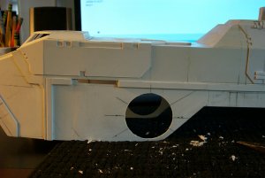
After gutting the foam from all but the ceiling of the forward bay and flight deck I find I have room to spare for all the goodies including the interior LEDs lighting.
I don't think I need go any further back into the structure because that would necessitate tearing out the wing roots and the landing gear housings and seriously compromise the entire structure of the aft superstructure; no that would be really bad.........
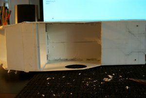
Anyway the cargo bay and ball turrets have a lot to keep me occupied for quite some time.
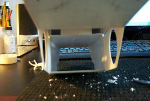
This interior shoot shows the inner space looking forward to the cargo door opening.
Beefing Up The Bevel Ring:
Looking at the Raven image below you can see that the gun mount ring immediately surrounding the turret itself is beveled on the inner rim.
Since I rarely use 2,0 MM styrene especially for precision holes the best way is IMHO is to sandwich flexible 2,0 MM strips between 1,0 MM gluing and clamping to hold the strip to the backing.
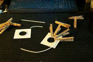
Since the bevel is quite thick a second strip is required as seen below.
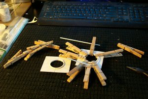
After the glue is dried all that is left is to patiently file a 45° bevel to the inner ring.
And with this I've used up my allotted ten image posts for today, thanks for watching............
Not yet anyway but working on it. I might just as well go for broke and install that cargo bay interior I've had in the back of my mind some time. Ever since I first saw these ball turrets.

After gutting the foam from all but the ceiling of the forward bay and flight deck I find I have room to spare for all the goodies including the interior LEDs lighting.
I don't think I need go any further back into the structure because that would necessitate tearing out the wing roots and the landing gear housings and seriously compromise the entire structure of the aft superstructure; no that would be really bad.........

Anyway the cargo bay and ball turrets have a lot to keep me occupied for quite some time.

This interior shoot shows the inner space looking forward to the cargo door opening.
Beefing Up The Bevel Ring:
Looking at the Raven image below you can see that the gun mount ring immediately surrounding the turret itself is beveled on the inner rim.

Since I rarely use 2,0 MM styrene especially for precision holes the best way is IMHO is to sandwich flexible 2,0 MM strips between 1,0 MM gluing and clamping to hold the strip to the backing.

Since the bevel is quite thick a second strip is required as seen below.

After the glue is dried all that is left is to patiently file a 45° bevel to the inner ring.
And with this I've used up my allotted ten image posts for today, thanks for watching............
The Thunderhawk Has Balls:
Just a dry run to see how everything fits. I have to open up the bevel a bit but the overall look is pretty good. The size seem alright not too small and not too big.
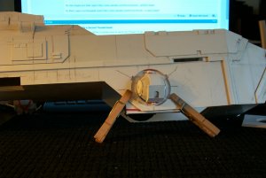
It's going to take some time to get use to how much the turret protrudes from the mount; once I enlarge the bevel I may recess the ball a few millimeters.
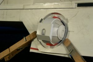
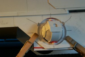
The next image just displays the range of movement of the turret:
And the last shows the bevel before I smooth the surface.
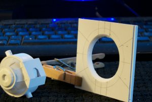
Just a dry run to see how everything fits. I have to open up the bevel a bit but the overall look is pretty good. The size seem alright not too small and not too big.

It's going to take some time to get use to how much the turret protrudes from the mount; once I enlarge the bevel I may recess the ball a few millimeters.

The next image just displays the range of movement of the turret:

And the last shows the bevel before I smooth the surface.

The Effort We Make:
I seem to be putting too much effort into a model I'm not all that enthused of working on but I have to keep reminding myself that I'm doing this for my son. Ha! He started this over seven years ago when he had just entered High School and this year he will be graduating College.
Anyway His kids might appreciate it.
Here is the T'hawk with Ball Turrets in place resting on it's nose gear
(Note the nose gear shock strut compressed with the gear deployed and the weight of the model resting on it.) I'm rather proud of that accomplishment. Actually, I'd forgotten I made that.
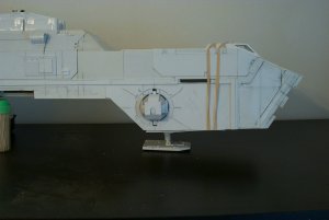
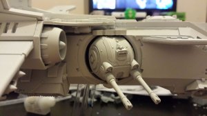
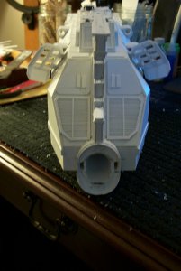
Here is the front view showing how much it protrudes from the side of the ship
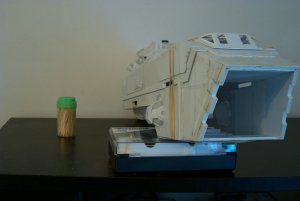
The temporary aligning straps are visible in this image but once the gun barrels are completed they will not be necessary.
Below we see a bottom view with the retractable landing gear exposed in the stowed position and the protrusion of the Ball Turret from the side is acceptable.
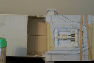
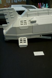
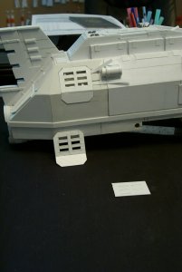
And again the retractable Landing gear this time in the deployed position with the landing pad (removed for clarity) in the foreground.
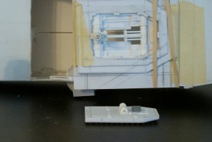
Just for those readers inquiring about the landing gears.
I'm extremely proud of my nose gear rendering as the actual mechanism occupies only 12,0 MM of space so therefore only protrudes 5,0 MM into the cargo bay floor. I always wondered what the FW model deployed landing strut looked like in the interior of the cargo bay.
An Engineering Tour de Farce:
Well I went blithefully ahead this week end whilst others were at play so the actual construction of the canard vanes went unrecorded.
Suffice it to say it was pretty much the same as the horizontal stabilizer albeit a tad smaller.
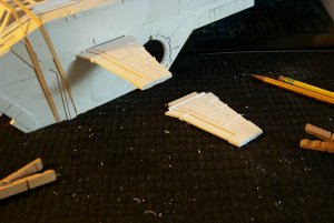
My Canards and tail plane structure is larger than both the 3D rendering and the FW model in relative size to the fuselage as my model is a bit more robust than either.
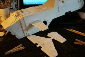
Once the Canard fixed guns are in place the extra length will be masked.
Came The Dawning!
Let it not be said that Blackadder doesn't need a safe dropped on him.......
This morning I have come to the realization that "all the major components for the Thunderhawk are built!!!!!"
Sooooo all that is left is the 'dessert'; the detail if you will.
Now The Blackadder loves to do detail and the more obscure the better so therefore I shall be starting on the underbelly first. (The interior and the wheel wells being already done.
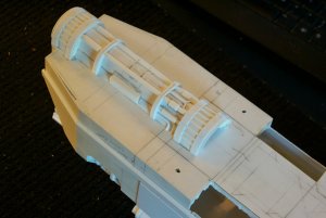
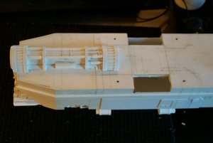
The above images show the barren underbelly as I left it a year or so ago and whilst I am about it I also need to strengthen the wing mounting so they don't droop and incorporate the mount into the underbelly detail as well.
I seem to be putting too much effort into a model I'm not all that enthused of working on but I have to keep reminding myself that I'm doing this for my son. Ha! He started this over seven years ago when he had just entered High School and this year he will be graduating College.
Anyway His kids might appreciate it.
Here is the T'hawk with Ball Turrets in place resting on it's nose gear
(Note the nose gear shock strut compressed with the gear deployed and the weight of the model resting on it.) I'm rather proud of that accomplishment. Actually, I'd forgotten I made that.

Here is the front view showing how much it protrudes from the side of the ship

The temporary aligning straps are visible in this image but once the gun barrels are completed they will not be necessary.
Below we see a bottom view with the retractable landing gear exposed in the stowed position and the protrusion of the Ball Turret from the side is acceptable.

And again the retractable Landing gear this time in the deployed position with the landing pad (removed for clarity) in the foreground.

Just for those readers inquiring about the landing gears.
I'm extremely proud of my nose gear rendering as the actual mechanism occupies only 12,0 MM of space so therefore only protrudes 5,0 MM into the cargo bay floor. I always wondered what the FW model deployed landing strut looked like in the interior of the cargo bay.
An Engineering Tour de Farce:
Well I went blithefully ahead this week end whilst others were at play so the actual construction of the canard vanes went unrecorded.
Suffice it to say it was pretty much the same as the horizontal stabilizer albeit a tad smaller.

My Canards and tail plane structure is larger than both the 3D rendering and the FW model in relative size to the fuselage as my model is a bit more robust than either.

Once the Canard fixed guns are in place the extra length will be masked.
Came The Dawning!
Let it not be said that Blackadder doesn't need a safe dropped on him.......
This morning I have come to the realization that "all the major components for the Thunderhawk are built!!!!!"
Sooooo all that is left is the 'dessert'; the detail if you will.
Now The Blackadder loves to do detail and the more obscure the better so therefore I shall be starting on the underbelly first. (The interior and the wheel wells being already done.


The above images show the barren underbelly as I left it a year or so ago and whilst I am about it I also need to strengthen the wing mounting so they don't droop and incorporate the mount into the underbelly detail as well.
Last edited:
Simple Round Louvered Vents:
A simple way to make the round louvered vents shown below.....
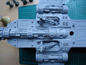
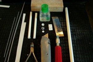
1. Glue thin rods or square stock to a piece of scrap thin sheeting. in this case I need 12 louvered vents 3/8 inch dia. and I used 0.025 inch rod for the grill.
2. I used thin ProWeld cement to adhere the rods to the 0.015 scrap sheet; when the glue began to gell I separated the rods with my finger nail to achieve consistent spacing.
3. Once I had sufficient louvers (In this case six.) I gave the assembly a final dose of cement to insure the rods will not come loose during the subsequent operations.
4. I then cut the proper sized squares of grill in this case 5/16 inch squares and glued them on to 5/16 inch tubing.
5. Once dried I rough trimmed the square grills to a vaguely round shape with the nail clippers shown and finished rounding the grill (Still attached to the 5/16th tubing.) with the sanding block shown.
6. After rounding the grill I separated the grill from the tube with the utility knife shown.
7. I cut a slim disk of 3/8 inch tube for the outer rim of the vent with the razor saw shown and sanded the rough edges with the sanding block. Shown again....
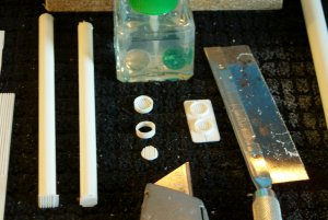
8. I glued the grill disk into the 3/8 inch tube housing and allowed to dry.
9. I glued the assembly to the precut fan panel for mounting on the underside of the T'hawk wing.
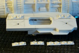
That's all the images allowed for today, thanks for watching.
A simple way to make the round louvered vents shown below.....


1. Glue thin rods or square stock to a piece of scrap thin sheeting. in this case I need 12 louvered vents 3/8 inch dia. and I used 0.025 inch rod for the grill.
2. I used thin ProWeld cement to adhere the rods to the 0.015 scrap sheet; when the glue began to gell I separated the rods with my finger nail to achieve consistent spacing.
3. Once I had sufficient louvers (In this case six.) I gave the assembly a final dose of cement to insure the rods will not come loose during the subsequent operations.
4. I then cut the proper sized squares of grill in this case 5/16 inch squares and glued them on to 5/16 inch tubing.
5. Once dried I rough trimmed the square grills to a vaguely round shape with the nail clippers shown and finished rounding the grill (Still attached to the 5/16th tubing.) with the sanding block shown.
6. After rounding the grill I separated the grill from the tube with the utility knife shown.
7. I cut a slim disk of 3/8 inch tube for the outer rim of the vent with the razor saw shown and sanded the rough edges with the sanding block. Shown again....

8. I glued the grill disk into the 3/8 inch tube housing and allowed to dry.
9. I glued the assembly to the precut fan panel for mounting on the underside of the T'hawk wing.

That's all the images allowed for today, thanks for watching.
Thanks, I have about six more pages of material to bring this Thunderhawk thread up to the present. Right now as we speak the T'hawk is in the process of being painted; I covered the entire model with a final primer coat of flat black just today.
The Unlikely Weapon:
Once again I must acquiesce to convention and add the ungainly Volcano cannon to my model; after all what is a Thunderhawk without this unseemly appendage?
Starting with the largest diameter tubing I have 13 MM (Half inch) I found I was short 3 MM in diameter of the Shadow Sword cannon's 16,0 MM maximum diameter.
Grabbing a page from my previous work on my scratchbuilt Warhound's ankles (Actually the 'instep' but we won't quibble,) I applied split half in sleeves to the basic core tubing to flesh out the diameter to 16,0 MM.
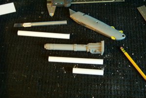
To add interest to the overall barrel I opted to step down the diameter toward the muzzle.
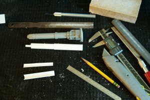
Naturally when sleeving the barrel there is produced a gap which I filled with inserts cut from scrap half inch tubing.
A progress report more than anything.
I am frequently asked how the details are made for these models.
Plasticard comes in such a wealth of shapes and sizes that actual shaping is a rare event.
Breaking the subject down to basic components is the way to go in scratch building.
Here we have the basic gun barrel stepped down a bit more in my version than in the original about a quarter millimeter but it should n't be a problem.
Evergreen tubing has the marvelous property of snugly telescoping the various sizes. I'm not sure any other manufacturers have that capability.
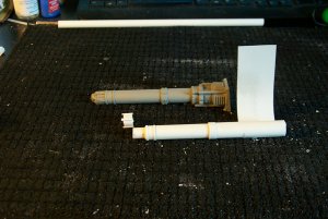
Here the muzzle is just about complete and the breech will have to be built up with a few layers of 0.020 inch sheet styrene.
Note the sheet styrene glued to the breech ready to be wrapped and glued to bulk up the breech end.
The barrel bands were attached in a similar fashion.
Before I get too far along I figured I'd better explain the processes that got me to this point. Of course if it all doesn't work out I will be just setting myself up for an embarrassing volte-face.
Employing the telescoping ability of the 'Evergreen' tubing I made reasonable facsimiles of the complex muzzle components.
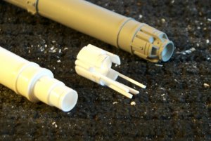
Right now I am in the process of duplicating the flash suppressor housing if that is what it is; naturally true to form I opted to make it 'inside out' or 'from the outside in' depending on your perspective.
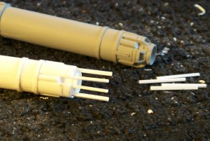
Once again I must acquiesce to convention and add the ungainly Volcano cannon to my model; after all what is a Thunderhawk without this unseemly appendage?
Starting with the largest diameter tubing I have 13 MM (Half inch) I found I was short 3 MM in diameter of the Shadow Sword cannon's 16,0 MM maximum diameter.
Grabbing a page from my previous work on my scratchbuilt Warhound's ankles (Actually the 'instep' but we won't quibble,) I applied split half in sleeves to the basic core tubing to flesh out the diameter to 16,0 MM.

To add interest to the overall barrel I opted to step down the diameter toward the muzzle.

Naturally when sleeving the barrel there is produced a gap which I filled with inserts cut from scrap half inch tubing.
A progress report more than anything.
I am frequently asked how the details are made for these models.
Plasticard comes in such a wealth of shapes and sizes that actual shaping is a rare event.
Breaking the subject down to basic components is the way to go in scratch building.
Here we have the basic gun barrel stepped down a bit more in my version than in the original about a quarter millimeter but it should n't be a problem.
Evergreen tubing has the marvelous property of snugly telescoping the various sizes. I'm not sure any other manufacturers have that capability.

Here the muzzle is just about complete and the breech will have to be built up with a few layers of 0.020 inch sheet styrene.
Note the sheet styrene glued to the breech ready to be wrapped and glued to bulk up the breech end.
The barrel bands were attached in a similar fashion.
Before I get too far along I figured I'd better explain the processes that got me to this point. Of course if it all doesn't work out I will be just setting myself up for an embarrassing volte-face.
Employing the telescoping ability of the 'Evergreen' tubing I made reasonable facsimiles of the complex muzzle components.

Right now I am in the process of duplicating the flash suppressor housing if that is what it is; naturally true to form I opted to make it 'inside out' or 'from the outside in' depending on your perspective.

Blackadder and the Lost Weekend:
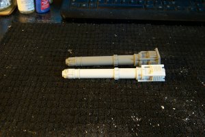
In spite of unfortunate necessary commitments I still manages to cobble together a reasonable facsimile of a Volcano cannon although the photo image reveals some barely acceptable flaws that board on intolerable.
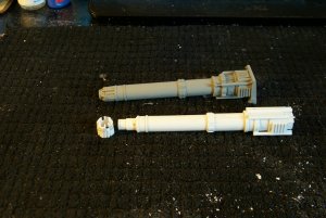
I'm rather pleased at the muzzle which was quite unnecessarily a cause for trepidation but the breech detail doesn't quite make the grade being too bulky and crude.
I'm hoping the addition of the rest of the appurtenances will bring the breech together and not promulge* a rebuild.
Fear of Flying:
I sometimes wonder when I embark on these projects what is my actual motivation.
Certainly I have great difficulty bringing each to completion. Granted Lucie is pretty much complete and the Warlord lacks only electronics and final painting.
The Tyranid army is going well, I have to practice more with my washes technique.
The Reaver project is stalled sadly because of lack of inspiration.
This Thunderhawk progress seems to be monopolizing all my work time this past week and I am greatly surprised and pleased with this my current work.
The Volcano Cannon has been a thorn in my side because I lacked the confidence to scratch build the fine detail.
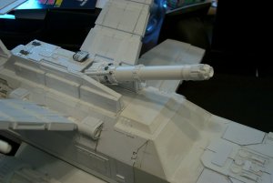
Well today for the first time I installed the completed cannon on its carriage mount and it fits the role satisfactorily.
Although appearing slightly smaller than the FW T'hawk's gun I think it suits the scale better overall. (It is in point of fact slightly longer than the FW cannon.)
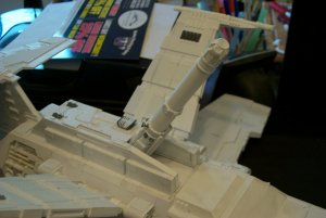
The trunnion mount affords a full range of elevation if that is actually necessary for a line of sight weapon.
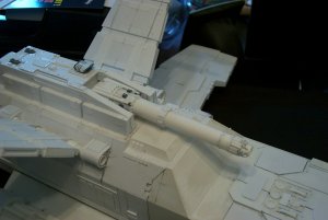
This side view shows the scale of the Volcano cannon in relation to my outsized Thunderhawk that I measured today at 750 MM / 29 inches; ten inches longer than the FW original.
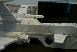
In spite of unfortunate necessary commitments I still manages to cobble together a reasonable facsimile of a Volcano cannon although the photo image reveals some barely acceptable flaws that board on intolerable.

I'm rather pleased at the muzzle which was quite unnecessarily a cause for trepidation but the breech detail doesn't quite make the grade being too bulky and crude.
I'm hoping the addition of the rest of the appurtenances will bring the breech together and not promulge* a rebuild.

Fear of Flying:
I sometimes wonder when I embark on these projects what is my actual motivation.
Certainly I have great difficulty bringing each to completion. Granted Lucie is pretty much complete and the Warlord lacks only electronics and final painting.
The Tyranid army is going well, I have to practice more with my washes technique.
The Reaver project is stalled sadly because of lack of inspiration.
This Thunderhawk progress seems to be monopolizing all my work time this past week and I am greatly surprised and pleased with this my current work.
The Volcano Cannon has been a thorn in my side because I lacked the confidence to scratch build the fine detail.

Well today for the first time I installed the completed cannon on its carriage mount and it fits the role satisfactorily.
Although appearing slightly smaller than the FW T'hawk's gun I think it suits the scale better overall. (It is in point of fact slightly longer than the FW cannon.)

The trunnion mount affords a full range of elevation if that is actually necessary for a line of sight weapon.

This side view shows the scale of the Volcano cannon in relation to my outsized Thunderhawk that I measured today at 750 MM / 29 inches; ten inches longer than the FW original.

Thank you for the reply,
Wingtips are a Drag:
Air spilling off the tip of a wing creates drag and lowers fuel economy so many modern aircraft have funny looking winglets on their tips to cut down on the wingtip vortices.
None are as strange looking as the constructions attached to the tips of the Thunderhawk. It seems the designers have gone out of their way to destroy anything vaguely resembling a lifting surface.
Below is my version of these tips liberally borrowing from half a dozen different 3D and Model designs.
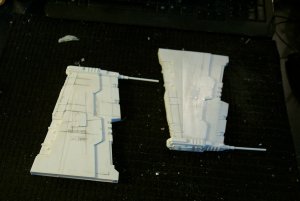
I made the tips detachable by installing six 3,0 MM magnets on each wingtip so the fragile stingers won't continually have to be replaced.
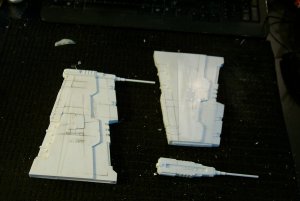
This pretty much spells finished to the wing detail although I may scribe lines to simulate flush panels if I feel the detail is too sparse.
Wingtips are a Drag:
Air spilling off the tip of a wing creates drag and lowers fuel economy so many modern aircraft have funny looking winglets on their tips to cut down on the wingtip vortices.
None are as strange looking as the constructions attached to the tips of the Thunderhawk. It seems the designers have gone out of their way to destroy anything vaguely resembling a lifting surface.
Below is my version of these tips liberally borrowing from half a dozen different 3D and Model designs.

I made the tips detachable by installing six 3,0 MM magnets on each wingtip so the fragile stingers won't continually have to be replaced.

This pretty much spells finished to the wing detail although I may scribe lines to simulate flush panels if I feel the detail is too sparse.


Air Brake Panels:
Cutting the slots in the air brake panels would be tedious except for one of the specialty items in the 'Evergreen' inventory.
In the 3/4 rear view below the air brake recesses have the hinge mechanisms I created years ago; all that needs be done is make the brake panes and glue them to the hinges.
To get the proper spacing of the six slots I used 'O' gauge boxcar siding available from 'Evergreen'.
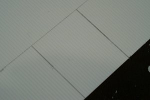
There it was a simple matter of scribing and punching out rectangular slots.
After reinforcing the back side and angle of the panel I installed the right side panel this morning;
No one has ever asked about the two thin strips of plastic cemented to the hinge points. These are tucked into the hinge slot and act to close off the hinge instead of a great gaping opening when the brakes are deployed. You'll see many such hinge covers on my models including the Volcano barrel mount in a subsequent post. I'll point it out when the time comes.
Well the air brakes are installed and are deploy-able but they are so laughably small as to appear ridiculous. How deploying such small panel can have any perceptible effect on slowing this flying brick outhouse is ludicrous.
Cutting the slots in the air brake panels would be tedious except for one of the specialty items in the 'Evergreen' inventory.
In the 3/4 rear view below the air brake recesses have the hinge mechanisms I created years ago; all that needs be done is make the brake panes and glue them to the hinges.

To get the proper spacing of the six slots I used 'O' gauge boxcar siding available from 'Evergreen'.


There it was a simple matter of scribing and punching out rectangular slots.

After reinforcing the back side and angle of the panel I installed the right side panel this morning;

No one has ever asked about the two thin strips of plastic cemented to the hinge points. These are tucked into the hinge slot and act to close off the hinge instead of a great gaping opening when the brakes are deployed. You'll see many such hinge covers on my models including the Volcano barrel mount in a subsequent post. I'll point it out when the time comes.

Well the air brakes are installed and are deploy-able but they are so laughably small as to appear ridiculous. How deploying such small panel can have any perceptible effect on slowing this flying brick outhouse is ludicrous.
Last edited:
111?
Well the air brakes are installed and are deploy-able but they are so laughably small as to appear ridiculous. How deploying such small panel can have any perceptible effect on slowing this flying brick outhouse is ludicrous.
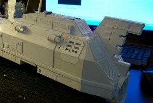
But they are on the original so they are on my model as well.
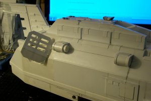
The left side air brake still needs to be adjusted but the right side brake works easily.
Zathros wanted to see the insignia so here is an Aquila.
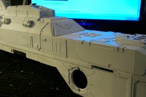
In case you were wondering about the title of this post 111 is the hull number of this craft.
Yeah if you think I chose this number because it was easiest to make you are probably right.
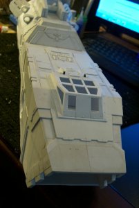
Meanwhile the interminable detailing proceeds and anther shot of the Aquila.
Well the air brakes are installed and are deploy-able but they are so laughably small as to appear ridiculous. How deploying such small panel can have any perceptible effect on slowing this flying brick outhouse is ludicrous.

But they are on the original so they are on my model as well.

The left side air brake still needs to be adjusted but the right side brake works easily.
Zathros wanted to see the insignia so here is an Aquila.

In case you were wondering about the title of this post 111 is the hull number of this craft.
Yeah if you think I chose this number because it was easiest to make you are probably right.

Meanwhile the interminable detailing proceeds and anther shot of the Aquila.
Last edited:
Way Too Much Effort:
I'm putting too much effort into a model I wasn't that enthused about in the first place.
But in for a penny as the saying goes.
There are some beautiful colour 3D renderings of T'hawks available and of all this is by far my favorite.
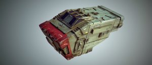
The rendering actually makes a T'hawk plausible and real.
The image above is the probable paint scheme I've decided on.
So since I am committed to finishing this model I may as well duplicate it the whole way and revamp the nose cowl/door.
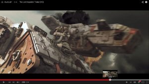
The front end of the 3D looks so much more brutal than the FW design..... Brutal is good....
Once I saw this 3D rendering I knew I wouldn't be satisfied with the basic T'hawk assault ramp.

A good shot of the Inquisitor insignia.
I'm putting too much effort into a model I wasn't that enthused about in the first place.
But in for a penny as the saying goes.
There are some beautiful colour 3D renderings of T'hawks available and of all this is by far my favorite.

The rendering actually makes a T'hawk plausible and real.

The image above is the probable paint scheme I've decided on.
So since I am committed to finishing this model I may as well duplicate it the whole way and revamp the nose cowl/door.

The front end of the 3D looks so much more brutal than the FW design..... Brutal is good....

Once I saw this 3D rendering I knew I wouldn't be satisfied with the basic T'hawk assault ramp.

A good shot of the Inquisitor insignia.
Attachments
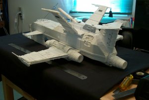
Thought I'd jump ahead to the present and show a picture of my T'hawk as she is right now, with hand rubbed aluminum powder over flat black primer to get this metallic effect.
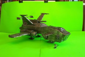
a teaser of things to come and there still is a lot of painting to do.............
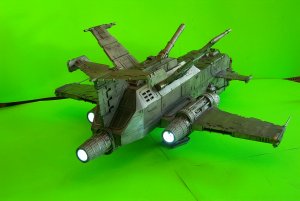
Yeah; she has lighted exhausts
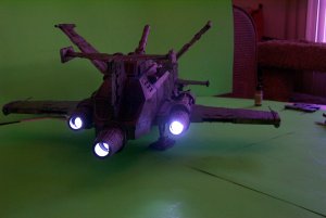
plus a slapdash photoshop image I cobbled together.
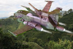
Crude I know but gives an idea of what I'm shooting for.
I'll continue to post images of how I reached this stage.............

a teaser of things to come and there still is a lot of painting to do.............

Yeah; she has lighted exhausts

plus a slapdash photoshop image I cobbled together.

Crude I know but gives an idea of what I'm shooting for.
I'll continue to post images of how I reached this stage.............
I like the metal look! I also like the lights in the exhaust.
You did a really good job with the photoshop as well.
You did a really good job with the photoshop as well.


