Bi-Color LEDs & DCC voltages

jimnrose

Member
Feb 1, 2001
137
0
16
Orleans Ma. USA
Visit site
I'm trying to use bi-color (red/green) leds as track signals indicators on a DCC system. The results are both diodes are turning on but at different currents yielding a yellowish light emittion. I tried buildingh a rectifier but am not using diodes that are fast enough to rectify the voltage. Does anyone know how I can build an expensive rectifier or another scheme where I can visually observe the track polarity (direction)?
Thanks, Jim
 

60103

Pooh Bah
Mar 25, 2002
4,754
0
36
Brampton, Ontario, Canada
Visit site
Jim:
In DCC the track polarity is changing constantly as that is what signals the chip to run the locomotive. You will not be able to see the LED changing colour that fast. Th DCC current is something like AC.
Also, direction does not come from the track, but from the chip. The only time you get something like DC on the track is when you run a DC loco on setting 0.
 

jimnrose

Member
Feb 1, 2001
137
0
16
Orleans Ma. USA
Visit site
David, thanks for your reply. The bi-color leds are two chips mounted in parallel. The red chip will be bright red in the forward direction and weak (partial) in the verse polarity and the green is similar. The color that is visualized is orange to yellow and varies slightly between diode sets.
On my layout I have many seperate circuits (like blocks) and can reverse the DCC to each block thru a DOPDT switch to manually reverse the train direction such as thru a loop or changing levels. I have 35 seperate circuits on five levels for 1200ft of track. It would be expensive to put auto reverse modules at every interface so I thought I would put a bi-color led at the strategic locations to show when I should change the appropriate DPDT switch.
I haven't seen the DCC pulse train on a scope but I'm guessing it's a square wave waveform that switches from 0 to +15v or 0 to -15v. If this is true then a high speed rectifier would modulate the polarity enough for a LED to either be on or off. If I can't accomplish this scheme then putting the LED across the gap on one rail (rather than across the track rails) may do the trick.
The Walthers catalogue has track signals for DC voltages and I'm trying to figure a way to build a similar inexpensive device for DCC.
Sorry for the lengthy details. Jim
 

seanm

Member
Oct 11, 2004
358
0
16
65
Sunny CA
www.pegnsean.net
(I am not stong on electronics... but)

Is it not also true that the color of the LED will vary due to the speed seetting of the analog channel (is that address 0?).... I understant it stretches length of the pulses on the either the + or the - side depending on direction and speed and this will effect the perceived color of the LED.... right?
 

jimnrose

Member
Feb 1, 2001
137
0
16
Orleans Ma. USA
Visit site
The intensity (or brightness) varies from each diode depending on the rep rate but the frequency doesn't change. When two diodes are mounted on one header/lens the combined colors from each diode will emit a color depending on the intensity of each diode (just like mining paiint colors). So a red and green (bi-color) set will emit a color that varies from yellow to orange depending on both the rep rate and variance between LED's because one diode is forward biased while the other is partially biased. That's my proble: how to modify the DCC voltage such that one doide will not turn on when the voltage polarity is reversed.
 

Gary Pfeil

Active Member
May 7, 2001
2,510
0
36
Boonton NJ
Visit site
Jim it sounds like you know more about electronics than me, but when you say you are using switches rather than auto reversng units to change the direction of trains, I think you mean changing the polarity of a section of track, no? The direction of a dcc controlled loco won't change but what you are doing is matching the polarity to the blocks on either side of this "reverse' block, to avoid a short when the loco bridgs the gaps. Am I understanding this correctly? And what you want is to know if the polarity of the switchable section of track matches the adjacent block you are about to run into? If I'm guessing all this correctly, lamps in a signal head could easily do this, a green lamp wired to opposite rails on different sides of the gap will light when polarity is matched. A red lamp wired to opposite sides of a gap in the same rail will light when the polarity doesn't match. Now using led's instead of lamps (seperate red and green) ought not to be a problem, but I'm sorry I don't have an answer for the bicolor led.
 

jimnrose

Member
Feb 1, 2001
137
0
16
Orleans Ma. USA
Visit site
Gary, your right that I'm using the DPDT switches just like the auto-reverse modules except I'm manually changing the track section polarity. The LED color tells me if a reversal is required. I believe lamps wouldn't do the trick because the filament will draw current independent of the voltage orientation.
Normally diodes are directional devices and draw current only in one direction which is ideal for a DC voltage control. The DCC pulses have rapid voltage swings called pulses that causes the diodes junction to partially draw current on the reverse side of the pulse thereby requiring a filter (rectifier) similar to converting AC voltage to DC (power supply). I'm not at my layout to build a rectifier and lack the knowledge on selecting high speed diodes for the rectifier. I received info that 1N4148's may do the trick.
Thanks for your input. Jim
 

capt_turk

Member
Nov 14, 2004
138
0
16
74
Green Cove Springs, Fla.
The speed of the diode should not be a consideration. DCC is at a realtively low frequency. Most any diode should work as long as the current rating is high enough to handle the load.
 

Gary Pfeil

Active Member
May 7, 2001
2,510
0
36
Boonton NJ
Visit site
Jim, You had me doubting myself for a second. The lamps work fine because it is either connected across the two rails, and will light, or is connected to the same rail, so it won't. I tried it. Here is a crude drawing. Leds would work just as well. But I have only used single color leds, not bicolor. Also, you can use the position of the toggle handle to indicate which end the reverse section will match.
 

Attachments

  • P1010610jpg..jpg
    P1010610jpg..jpg
    24.9 KB · Views: 143

Gary Pfeil

Active Member
May 7, 2001
2,510
0
36
Boonton NJ
Visit site
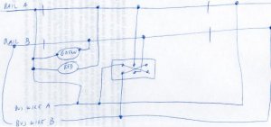
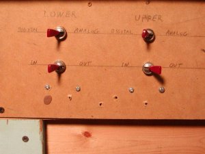
Here's a picture of a panel almost as crude as my drawing. I built it to allow operation of analog locos on my bottom level mainline. Basically the layout on the bottom level consists of a double track mainline with staging reverse loops at each end. One end has three reverse blocks, the other 5. I made one of the blocks at each end able to bypass the auto reverser (the digital/analog switch) When in analog, the other switch is in the circuit, and aligns the polarity of the reverse block with either the inbound or outbound end. This is what I referred to in my last post, using the handle of a toggle to indicate which way the polarity is set. Wouldn't have been hard to install lights or leds but I felt it wasn't needed. BTW, after using the toggles initially, they haven't been used in years, I don't want to throw toggles! I just don't run analog except to test prior to decoder installation, so don't need to run them into the reverse blocks. Hope some of this helps.

Gary
 

Attachments

  • P1010611jpg..jpg
    P1010611jpg..jpg
    50.6 KB · Views: 144

jimnrose

Member
Feb 1, 2001
137
0
16
Orleans Ma. USA
Visit site
Gary, great help. It will be much easier to stick with bulbs than diodes and your circuit having oner bulb across the gap (red) and the other (green) across the tracks, will not only do the job but be much simpler & cheaper.
Thanks for solving my problem that has been festering for quite a while.
Thanks, Jim