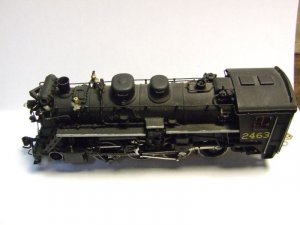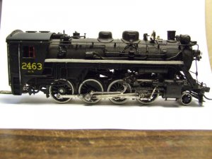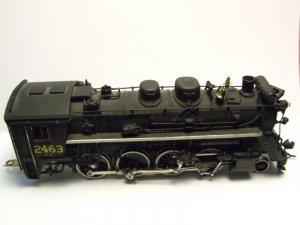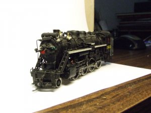
Van Hobbies brass CNR N-5-d 2-8-0 rebuild

WReid

New Member
Jan 26, 2008
69
0
6
Kirkland Lake, Ontario
New #2760.jpg
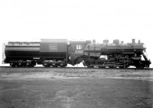
While looking at some old photos I found this one. It is a builders shot of #2760. All nice and shiny new with the vanderbilt tender built for it. The vanderbilt tender is nice but it does look a little to big behind a 2-8-0.

Now for some pictures of the reassembled drive for my N-5-d.
reassembled drive right side.jpg
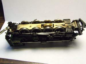
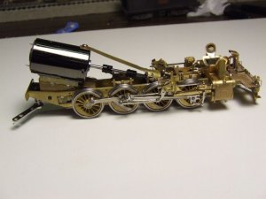
Here is a right side view of the assembled drive. The new drivers and springs, the new gearbox with new drive shaft couplers, a torque arm, modified motor mount and the can motor.
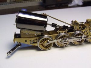
motor mounted.jpg
A close up view of the new can motor and the motor mount. I ended up using a different motor. This one had a single shaft and is 2mm longer than the other one. The motor is being held in place by some double sided foam tape. Same stuff used to mount after market plastic body panels on cars. Very strong stuff.
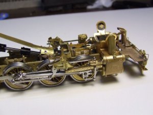
valve gear.jpg
The valve gear has been cleaned up and remounted for test running.
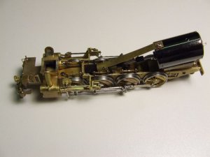
drive top view.jpg
A top view of the reassembled drive showing the torque arm. Seeing as the gearbox floats on the axle of the geared driver it is needed to stop the gearbox from flopping forwards and backwards. I made it from some 0.015" brass sheet. The end at the gearbox was formed to match the top of the gearbox. The gearbox has two holes drilled and tapped for 1.4mm screws. They hold the torque arm on the gearbox. The torque arm is attached to the motor with a 2mm shouldered screw. This allows the geared driver some side to side movement for curves.

The assembled drive was wired for DC power and test ran with the rebuilt tender after the above photos were taken. The good news is it ran good but did have some issues with the side rod clearances and some small rubs and binds. A few thin thrust washers, some careful bending and a little filling took care of the problems. It now runs very well and is very quiet. I have a couple of Proto 2000 Heritage 0-8-0s in CN markings and it runs just about as well as they do. The low speed is nice and it will crawl along slow enough it takes about 30 seconds to cover three feet. The gearbox is new so hopefully with some running the slow speed will get slower yet.

Next was a test run with a DCC decoder. I rewired the drive for a Digitrax DH163 decoder. The preformance was the same except for the slow speed. The decoder has adjustments to help slow speed control and they made a difference. It will now creep along slow enough that a three foot stretch takes under a minute. I must say I am very pleased with the results. Seeing as it was a well run locomotive that was not taken care of I expected a bit of a struggle when it came to getting it to run smoothly and slow.

Next posting will be some pictures of the drive with the boiler remounted. I just need to download them off my camera and resize them.


Wayne R
 

60103

Pooh Bah
Mar 25, 2002
4,754
0
36
Brampton, Ontario, Canada
Visit site
Wayne: do you need any etra tools with the Quarterer? I looked at it in the LHS and it seemed to need a drill press or something. Can you use it with less impressive tools?
The new puller has some mods. Mine goes back to the mid 1970s; I bought it for N scale but it works well with OO.
 

WReid

New Member
Jan 26, 2008
69
0
6
Kirkland Lake, Ontario
The new Quarterer II ( the one in my picture ) does not need a drill press. A small vice or a small c-clamp comes in handy for wheels with very tight axle holes. I have a small vice so I used it. If you look at the picture you will see two brass round bump outs ( one on each side piece of the jig ). Pressure is supposed to be applied there to press the axle back into the wheel. The trick is to make sure the wheel is a perfect 90 degrees to the axle before pressing them back together. The jig comes with some machined brass index pins. You must use a screw with the proper threads to screw them to your drivers. When I bought my Quarterer I also bought the optional machined index pins that are threaded and ready to use. I also bought the optional index pins because my crankpin screws are an oddball size ( 1/16 x 60W ). Finding screws that thread type is hard.

When I did my driver sets it took me about 5 minutes per axle to quarter them. I found the jig to be very easy to use and it worked very well. I have tried their cheaper one as well. It works fine but was a little harder to use and I found it to be not as accurate.

One thing I forgot to mention is my new drivers came with 1.4mm threaded crankpins holes. :curse: The original Van Hobbies drivers used 1/16 x 60W crankpin screws. Seeing as I had no luck finding some 1.4mm crankpin screws that would work with my side rods.wall1 I ended up buying a 1/16 x 60W tape and drill set. I was able to drill and tap the 1.4mm holes to 1/16 x 60W. I then just reused the original crankpin screws and the side rods fit the new drivers with no problems.


Wayne R
 

WReid

New Member
Jan 26, 2008
69
0
6
Kirkland Lake, Ontario
Well still no sound decoder and speaker as of yet. Hopefully it is in tomorrows mail. Once I have it I will be able to drill some holes in the tender floor for the speaker and finish rewiring the drive. After a little test run I will be able to tear down the drive and get the remaining parts ready for paint.

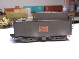
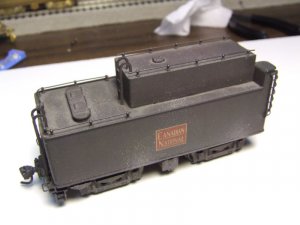
I had put out a request a while back looking for a spare tender for a N-5-d on some other forums. I am going to need one for N-5-d #2 as the tender that came with it is for the most part junk.Only the main tender body and the floor are possibly usable. The oil bunker was cut up into 6 pieces.:eek:
I got a couple of replies and was able to purchase two other tenders a month ago .One was painted with floquil paint and decaled. The other had paint and no decals. The paint was real heavy and looked like it was done with a hardware store spray can. Today I finally stripped the paint from both. The one with the poor paint job was easy as a bath in lacquer thinner had the paint off in less than 20 minutes. This one was missing a rear step so I salvaged one from the floor of the destroyed tender and soldered it on.
Removing the paint from the tender that was painted with floquil paint and decaled proved to be a much harder job. The paint must have been baked on as after 2 hours in lacquer thinner it was not coming off. :confused: I finally got the paint off by sandblasting the tender and frame with baking soda. A messy job but the paint came off without too much trouble.

new tender ( a ).jpg

new tender ( b ).jpg
The two pictures show the floquil painted tender before I removed the paint. The paint job was okay except for the weathering. I also found the paint to be to grey looking. Easier to remove the paint and repaint with my black.

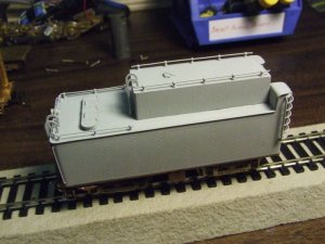
primed tender.jpg
This is the second tender I purchased. The shell has been primed to keep it from tarnishing. The floquil painted tender was left unpainted and is stored in a plastic ziplock baggies to keep it out of the air so it does not tarnish. I will be using it with the locomotive instead of the tender I repaired.

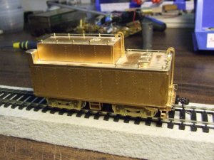
Even though I aready have three usable tenders and only two N-5-d locomotives that need tender I ended up buying another tender. I was given a tip about this one sitting on a hobby shop shelf. The price was really good so I bought it. It arrived in todays mail.

brass tender a.jpg

brass tender b.jpg
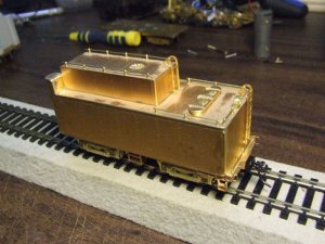
This one is new and unused and has a clear lacquer coating on it. It does have some minor tarnish spots under the clear coating but for now it will be staying as is.
This tender may end up behind a Genesis 2-8-2 sometime this winter.


Wayne R
 

WReid

New Member
Jan 26, 2008
69
0
6
Kirkland Lake, Ontario
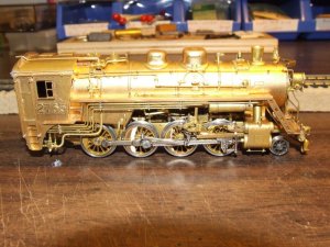
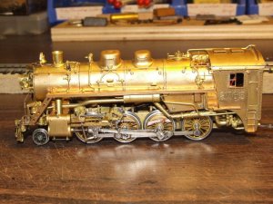
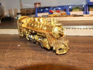
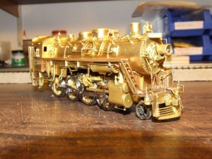
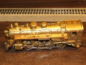
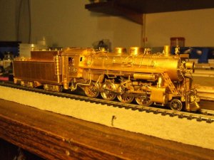
The pictures below show the repaired drive with the boiler mounted back on it. When the photos were taken it was being test on DCC and has a Digitrax decoder in the boiler. I had thought about replacing some of the factory details with new details that have a little more detail to them but decided to leave things as is. I am happy with the factory details. I am also very happy with how well things have turned out.
The pilot was in pieces when I got the locomotive as was the H handrail in front of the smokebox front. The pilot was soldered back together and a new uncoupling lever bent from 0.015 brass wire. The front H handrail was rebuilt from a few original parts and some brass wire.
The headlight and smoke box front were already drilled for a lightbulb so I will be installing a MV Products lens and a micro golden white LED headlight once everything is painted, decaled and clear coated.

locomotive right side.jpg

locomotive left side.jpg

locomotive front 1.jpg

locomotive front 2.jpg

locomotive top.jpg

locomotive cab.jpg
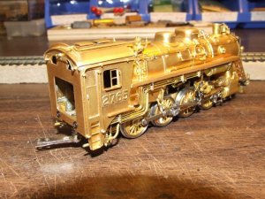
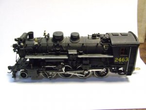
The photos show the etched brass cab numbers I have aded to the cab. I decided to number this locomotive #2765. The full size #2765 was assigned to Smithers, British Columbia.

The etched brass cab numbers were glued in place with 5 minute epoxy. They were done one at a time. I mixed up a small puddle of epoxy and floated the cab number on it backside down for a few seconds. The number was then placed on the cab in the location I wanted it, aligned and pressed down. Once the epoxy reached a taffy like stage the extra that squeezed out around the number was removed with the tip of an x-acto blade.

The boiler for the most part was in really good shape underneath all the heavy paint. I only had to repair a few cracked solder joints and rebend a few bent handrails. There was a little tarnish under the paint but nothing serious. This was the easiest part of the whole restoration so far.

The boiler, smokebox front, pilot and steps have now been sandblasted and are in ziplock baggies awaiting painting. I am hoping to paint them this weekend.


Wayne R
 

WReid

New Member
Jan 26, 2008
69
0
6
Kirkland Lake, Ontario
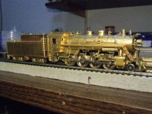
This morning I took a couple of quick pictures of the locomotive and the clear coated brass tender together.

loco & tender 1.jpg

loco & tender 2.jpg
When I took this picture I was playing around with my Digital cameras light settings. I thought this picture was kind of neat as it has an old time look.


The following pictures are of the tender I received with the second locomotive I bought. The one with the destroyed oil bunker.

L2 tender pic A.jpg
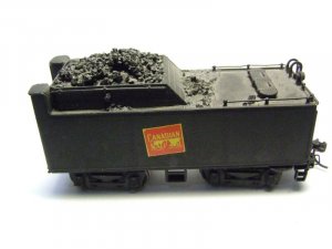
This shot shows the CPR coal bunker that was added after the original owner removed the oil bunker. It has a Canadian look but for a real CNR fan it is not correct.

L2  tender pic B.jpg
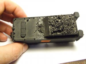
This top view shows that the coal bunker was not glued on straight. The small pile of coal betwen the rear of the coal bunker and the water hatch is covering up the remaining hole left from the oil bunker removal that the coal bunker did not cover.

The way this tender looks in the pictures is for the most part how the tender I repaired looked before I removed the coal bunker and the paint.

Seeing as the oil bunker for the tender above is a bunch of cut up parts I may just end up making the needed changes to the main tender body and fabricate the needed parts from brass to turn it into a coal tender. I am sure with a little careful work and soldering it can be done. I have some HO and S scale drawings of the oil and coal tenders used behind the N-5-d class so I have something to work from.


Wayne R
 

WReid

New Member
Jan 26, 2008
69
0
6
Kirkland Lake, Ontario
Below are some more pictures of the second N-5-d I purchased with the first one. This one is going to require a lot more work to restore. Once I get locomotive #1 done this one will be next.

L2 left side A.jpg

L2 left side top view.jpg
These two pictures show the left side. At some time an Elesco feedwater heater system has been added by someone. In doing so they have cut out a section of the left side running board and relocated it above part of the feedwater system. The N-5-d class never had this type of feedwater system. I am guessing they were trying to make it look like a N-4 class locomotive which had an open cab instead of vestibule cab. The feedwater system parts all seemed to be glued on.

L2 right side A.jpg

L2 right side top view.jpg
The right side is for the most part unmodified. There is an extra detail part on top the running board and some extra piping for the feedwater system and the bell has been relocated. These extra parts seemed to be glued on as well and possibly a hole drilled in the boiler to relocate the bell.

L2 front view.jpg
The front of the locomotive has a few problems. The pilot has had the solder joints broken and has been glued. The airpump and airpump sheild has been removed from the pilot. The headlight and headlight bracket seems to be made of plastic tubing and sheet stock and the front H handrail is in bad shape. The good news is I have the airpump and airpump sheild.

L2 bottom view.jpg
Here is a bottom view showing the original factory gearbox still in place. I am not sure but it looks like this locomotive was painted without taking it apart. The drivers have a lot of wear on this one and some wheels have no plating left. Surprisingly this one actually ran not to bad. It had a little gear noise and bit of a bind problem a real low speeds but for the most part ran good for a well used old brass locomotive. Most of all since some of the older Van Hobbies CNR brass from the 1970s are know to have problems.


Wayne R
 

doctorwayne

Active Member
Sep 6, 2005
3,516
0
36
Canada, eh?
At some time an Elesco feedwater heater system has been added by someone. In doing so they have cut out a section of the left side running board and relocated it above part of the feedwater system. The N-5-d class never had this type of feedwater system. I am guessing they were trying to make it look like a N-4 class locomotive which had an open cab instead of vestibule cab. The feedwater system parts all seemed to be glued on.
Wayne R
Your restoration work is looking good, Wayne. Judging by the number, the original owner of the second loco was trying to make it into an N-2-b, which did have an Elesco fwh, but not the vestibule cab. I'm building a couple of these from the Bachmann Consolidation, along with a DW&P N-2-a. A package of parts arrived this morning, :-D but at the rate I work, I'll wait until the project is finished before I post any pictures. ;)
The gizmo atop the running board on the engineer's side, by the way, is a trap for removing oil from the condensate from the heater. The cleaned condensate is piped back to the tender.

Wayne
 

WReid

New Member
Jan 26, 2008
69
0
6
Kirkland Lake, Ontario
Your restoration work is looking good, Wayne. Judging by the number, the original owner of the second loco was trying to make it into an N-2-b, which did have an Elesco fwh, but not the vestibule cab. I'm building a couple of these from the Bachmann Consolidation, along with a DW&P N-2-a. A package of parts arrived this morning, :grin: but at the rate I work, I'll wait until the project is finished before I post any pictures. :wink:
The gizmo atop the running board on the engineer's side, by the way, is a trap for removing oil from the condensate from the heater. The cleaned condensate is piped back to the tender.

Wayne

Wayne

Thanks for the info. I have been meaning to check the cab number to see what class he was trying to model but never got there. I am looking forward to your Bachmann Consolidation N-2-b conversion. I have a couple of them and was thinking of doing the same thing to. I am also thinking of kitbashing one into a Central Vermont N-5-a. Model Railroader had an article in the Nov. 1999 issue.

I was also planning on holding off posting my N-5-d restoration project until I got it finished. Seeing as I was close to paint time I decided to go ahead and start posting what I had already done. :) Seeing as my sound decoder was on its way I figured by the time I finished the posting the work that was done the decoder would be here and I would be on track to smoothly post the rest of the restoration. Of course the decoder and speaker have not shown up yet. :curse: Looks like my plans for a smooth posting may have wrench thrown in the works. wall1 The good news is I can always do some work on the second one and post that.


Wayne R
 

WReid

New Member
Jan 26, 2008
69
0
6
Kirkland Lake, Ontario
Well unforunatly I was unable to get any painting done this weekend. Other things kept me from working on the N-5-d.

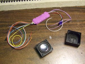
The good news is Monday morning the Soundtraxx Tsunami sound decoder, speaker and speaker box showed up in the mail finally.

decoder & speaker.jpg
The Tsunami light steam decoder, speaker and speaker box I will be using.

speaker & box.jpg
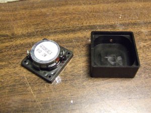
A shot of the speaker & speaker box. The box seals the back side of the speaker which makes for better sound preformance.

I spent Monday afternoon and evening planning out the sound install. My first hurdle was to decide how to get the sound out of the tender. I really was hoping to avoid drilling any holes but seeing as the tender is an oil tender I have no coal bunker to mount the speaker in. My other steam locomotives I installed Tsunami decoders in have the speaker mount facing up in the coal bunker with a piece of carved soft foam sponge with some coal glued to it hidding the speaker.

The first thing I did was test the sound decoder to make sure it was working fine. I do this with all new decoders before installing them. Next I decided to see how things would sound with the speaker in its box facing up inside the tender. Needless to say even with the volume turned all the way up the sound level was low and the sound quality was poor.

This left me with one option. Drill some holes. Seeing as the oil bunker made getting the sound out via the top of the shell impossible I was left with the tender floor. Also seeing as I had to get six wires from the locomotive into the tender it and space is at a premium at the front of the tender floor it meant the speaker would be at the back of the tender.

drilling template.jpg
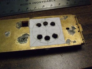
The tender floor with a drilling template I made to help drill the holes where they would not be effected by things on the bottom of the tender.I was only able to drill six holes.

speaker setup.jpg
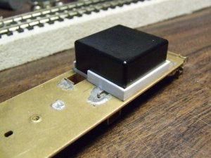
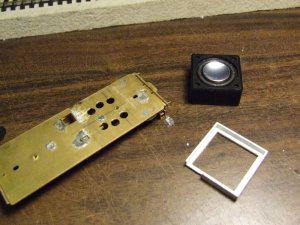
This is how the speaker will be mounted. The white plastic frame the speaker box is sitting in was need because the speakers cone was touching the tender floor. I made the spacer from some .060" & .040" styrene plastic strips.

speaker assembly parts.jpg
The drilled tender floor, speaker setup and the spacer I made.


Waye R
 

steamhead

Active Member
Apr 16, 2005
2,360
0
36
75
Brownsville, TX
That's coming along nicely....I like your step-by-step...It'll be useful for when I tackle my little 0-8-0 that wobbles....(After I changed the gear tower....wall1).
 

WReid

New Member
Jan 26, 2008
69
0
6
Kirkland Lake, Ontario
Now that I got the speaker mounting sorted out I needed to figure out where to have the six wires needed exit the tender. Needed are 2 motor leads, 2 power leads as the front part of the locomotive will be picking up power from both rails and 2 wires for the headlight. I also had to decide if I was going to use micro plugs so the locomotive and tender could be seperated if needed.

There were two problems I could see if I used the micro plugs.
#1 was they are not rated for more than 500 mah. Okay for the headlight but not so good for the motor or the power feeds.
#2 Due to the design of the tender there was no space under the tender for them and no real good spot under the cab either. Even though they are micro plugs they are still fair sized so leaving them hanging between the tender and cab was not an option either.

I wanted an clean setup and to be honest I rarely seperate the tender from my plastic steam locomotives and they all have built in plugs. I decided to hardwire the tender to the locomotive in such a way I could still seperate them without to much hassle.

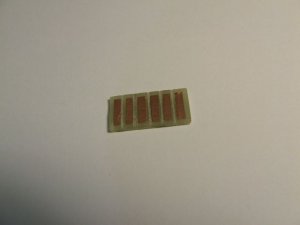
circuit board connector.jpg
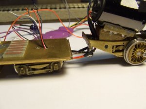
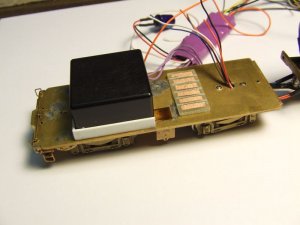
Using a kit for making circuit boards and some single sided circuit board I made this little piece. It measures 1.2" x .5" and has 6 contact srtips. It started off as a piece of copper coated circuit board blank. Using 1/16 pinstripping I masked the copper areas I wanted to etch off with the acid included in the kit. I was left with 6 strips 3/32" wide which were painted over with clear lacquer to protect the copper. The pinstripping was then removed and the board placed in the acid. When it came out I was left spaces between the pads and around the perimeter of the board. I also filed a small grove with a small triangular file between each pad to make sure they were all isolated from each other.

wires to tender.jpg
To route the wires into the tender I drilled a 1/8" hole just in front of the front truck mounting point. The wires exit as two groups of three from under the cab and are routed one on each side of the draw bar. I would have liked to have them enter the tender closer to the tender front but due to the design of the tender front wall and a mounting screw for the tender shell being in the way this was my best option.

tender electronics set up.jpg
This photo shows the speaker sitting in place and the circuit board I made. The circuit board will be stuck to the tender floor with some double sided tape in the postion shown in the photo. The six wires from the decoder will each be soldered to one end of each of the copper strips. The wires coming up through the tender floor from the locomotive will go the the other end of the copper strips. All the wires from the locomotive have been color coded to match the decoder wires.

If I ever need to seperate the tender I will just have to remove the tender shell and unsolder from the circuit board the six wires from the locomotive and pull them down through the hole. For safety the circuit board will be covered with some tape once the connections are made. No exposed contacts for this guy.

The decoder will be placed in the top of the tender shell up in the oil bunker. The wires between the locomotive and tender will be painted black so they look like hoses.


Wayne R
 

tetters

Rail Spiking Fool!
Jan 21, 2005
879
0
16
50
Toronto, Ontario, Canada
That is pretty cool. I'm loving the step by step. I like the PCB connection idea. It's too bad that you'd have to unsolder your connections though just to separate the tender from the loco. I know from experience that repeated soldering of PCB's will eventually destroy the adhesion between the fiberglass board and the copper cladding. However, I suppose that its easy enough to replace should you need too.
 

WReid

New Member
Jan 26, 2008
69
0
6
Kirkland Lake, Ontario
I would have liked to use micro plugs but two 3 wire plugs were just too hard to hide. The front truck on the tender being so close to the tender front makes it impossible to hide the plugs under the tender. The enclosed cab was another thought as I could hide the plugs inside the back of the cab but the motor took up just about all the space and the hole in the cab back wall was a little too small to be trying to plug things in through. Under the cab was a problem also as they would have hung down enough to be unsightly and there is not much room to tuck them up into.

Also as I mentioned in my last post the plugs were only rated for 500 mah. The current rating was fine for the headlight and possibly the motor but for the power feeds I did not trust them. I have a meter that shows me how many amps my Digitrax DCC system is being asked to supply and tests showed with the sound on and the locomotive under load 1 amp or more was possible at times.

I actually planned ahead with my circuit board idea. Seeing as I would need another one for the second N-5-d I will be rebuilding I spent a couple of hours last night and acid etched another 7 of them.:eek: I should be good for awhile.I hope.


Wayne R
 

tetters

Rail Spiking Fool!
Jan 21, 2005
879
0
16
50
Toronto, Ontario, Canada
You are leaps and bounds ahead of me in terms of expertise Wayne. I wouldn't even know where to start in terms of a rebuild like the one you are doing. I don't even own a brass loco, in fact such a purchase is no where near my "to do" list. Sounds like you have a solid plan with the spare boards all etched out though. ;-) Still, can't wait to see the paint applications. Awesome restoration work.
 

MasonJar

It's not rocket surgery
Oct 31, 2002
5,362
0
36
Ottawa, Canada
Visit site
Wayne...

Great stuff! :thumb: thumb: You are doing some excellent work! And the fact that your engines are destined to be CNR models is the icing on the cake... ;) :D

Andrew