diode matrix
You can reduce the number of controls required.
I use a system where there are contacts on the control panel track dagram and a dangling wire; you could use push buttons.
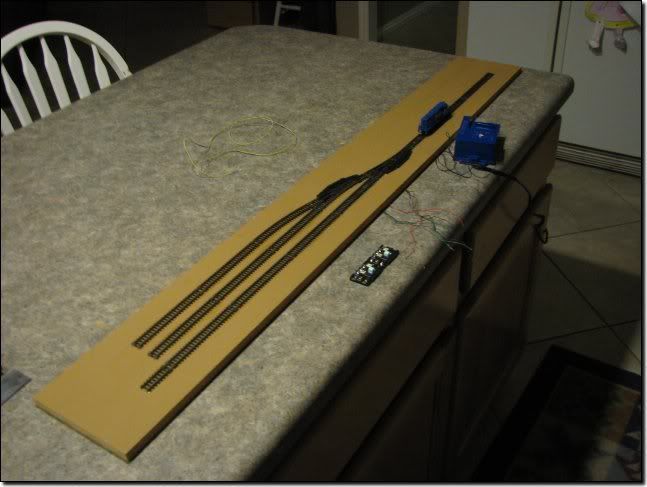
Using jesso's track plan as an example: you can set up a diode matrix for control. There are engineering-style designs for these, but for simplicity, I'll describe it. You have 3 pushbuttons for each of the sidings, 1 2 and 3 from the bottom. The turnouts are A and B from the bottom.
Button 1 throws turnout A straight.
Button 2 throws turnout B curved and turnout A curved.
Button 3 throws turnout B straight and turnout A curved.
Button 3 is connected to one side of turnout B motor and through a diode to the curved side of turnout A.
Button 2 is connected to the other side of turnout B motor and through a diode to the curved side of turnout A. (Both diodes end up on the same side of turnout A).
When 2 is pushed, it curves turnout B and through the diode turnout A. The other diode prevents the current from coming back to the straight side of turnout B. Similarly for 3.
I think a DC supply is needed but I may be wrong. This method can be expanded and applied to complicated systems. If you have a lot of turnouts at one time you may need a Capacitor Discharge Unit.