1880's paycar

nkp174

Active Member
Oct 10, 2006
1,455
0
36
41
Cincinnati, O.
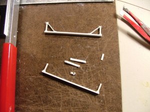
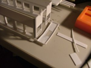
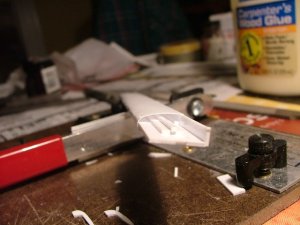
I'm experimenting with different door designs (I don't really know what the C&S 911 has...nor what it had in its previous life as DSP&P 051). The door has to be opening for me. I'm going to go back to the composite overlays...because I didn't like the results of the cut out method...I did essentially finish it and it looks much nicer than in this picture.

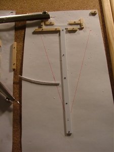
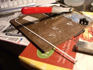
I'll be starting the brake gear once I've figured out (with my freight cars) how to build it (the layouts in 1884 were far more similar than now...the development diverged greatly between 1884 and 1900).

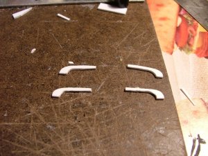
This door will go in my scrap box...maybe to be resurrected some day for a structure or something.
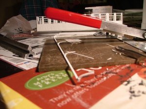
 

Attachments

  • p1.JPG
    p1.JPG
    127.6 KB · Views: 7

MasonJar

It's not rocket surgery
Oct 31, 2002
5,362
0
36
Ottawa, Canada
Visit site
Or just keep your eyes to the ground when you walk down the street. I find tire weights all the time. For awhile I would collect them, then melt them in a soup can with a propane torch, and let them cool into little round ingots for storage. If I ever need lead for something, I can reheat it and pour it into a mold of whatever shape I want.

Kevin

Just make sure you're using adequate ventilation AND an appropriate mask!

Andrew
 

nkp174

Active Member
Oct 10, 2006
1,455
0
36
41
Cincinnati, O.
Here's my first couple attempts at the roof.

First is my L frame which supports/holds the roof.

Second are a few carlines (or rafters...I believe...carlines are the ones in the clerestory...I think). These are an attempt at prototypical construction and have been derived from White's American Railroad Passenger Car (my favorite book). The allow the car to have the accurate 100cu ft of headspace above the seats.

I'm going to build the brake gear...either during or immediately after I finish the roof.
 

Attachments

  • roof arch1.JPG
    roof arch1.JPG
    122.2 KB · Views: 8
  • carlines.JPG
    carlines.JPG
    132.1 KB · Views: 6

nkp174

Active Member
Oct 10, 2006
1,455
0
36
41
Cincinnati, O.
Well, I've got the bottom half of the roof frame completed...aside from the bull nose ends. I still need to build the frame for the top of the clerestory. Regardless, the last several steps on this were very exciting. It is pretty much prototypical construction...but with a dramatically reduced # of braces.

I can explain techniques if anyone is interested.
 

Attachments

  • 4.JPG
    4.JPG
    135.7 KB · Views: 12
  • 5.JPG
    5.JPG
    123.9 KB · Views: 9
  • DSCF5839.JPG
    DSCF5839.JPG
    123.9 KB · Views: 8
  • DSCF5842.JPG
    DSCF5842.JPG
    120.4 KB · Views: 10
  • fin.JPG
    fin.JPG
    111.5 KB · Views: 10

doctorwayne

Active Member
Sep 6, 2005
3,516
0
36
Canada, eh?
More nice work, as usual, Michael, but I think that you might be wise to add a few more braces. While the curve in the sheathing material will add some measure of structural strength when everything is assembled, I'd be concerned that .010" styrene will eventually sag somewhat between the supports - not at the curve, but along the flat areas. Just an opinion, but I think you might prevent future problems by adding two or three supports between the ones that you already have in place. Is the roof going to be removeable? If so, are you planning on finishing the underside of the roof with some sort of ceiling? That would add to the structural integrity of the roof, but I still feel that you might eventually regret not adding the extra support. For the amount of skill and effort that you're putting into this, it would truly be a shame if the roof did deform over time, all for want of a few more supports. However, that's just my thoughts on this, as you've gone far beyond what I would attempt.
I'm sure that you've also got a plan in mind for the ends of the roof, but if not, how about "board by board" construction - you could taper the individual boards to accomodate the compound curves, and then cover the roof with "canvas", which I assume is what the prototype used. I just modified a caboose roof by covering it in "canvas" made from tissue, and while it worked well, the multiple applications of lacquer thinner might not be too kind to .010" styrene.
Keep up the good work - nice to see that the art of scratchbuilding is truly alive. :thumb:

Wayne
 

nkp174

Active Member
Oct 10, 2006
1,455
0
36
41
Cincinnati, O.
Some intriguing ideas.

You can't see them, but there are supports running the length of the car...in between the arches. But, I am concerned with the middle sagging. I'm hoping that the clerestory will add some additional support...but it could still sag. I've got to do a good job of attaching the top for the clerestory so that it resists this bending.

Actually, come to think of it, the 0.010" thick styrene will have some spring to it which ought to pull the middle of the car up...as I'm not going to be heating & forming it.

Yes, the plan is for the roof to be removable. I won't be finishing the interior for a while (I can't find any sources for the interior of a pay car...aside from the basics: a safe, a pay master's desk, and a place to distribute the pay. When I do finish the interior, the roof will receive a layer of internal sheathing. Between now and then, I might add some additional supports...I stopped where I did because they were time consuming to make...and more importantly...my fingers started to cramp up while holding the tiny pieces to file them :rolleyes:.

Good ideas on the ends...I haven't given it too much throught yet...aside from that the fascia ought to be a single piece. Board by board definitely has much potential in applications like this. I've thought about it a few times...although not specifically for the end as you've described...where the 0.010" styrene would cause plenty of trouble.

I don't know if this car had a tin or canvas roof. I can recall around 5 years ago when I brought tissue from work to use for a canvas roof on a pair of MDC overton HOn3 kitbashed passenger cars...Which I never got around to completing. (although the combine is in service...just without couplers). It is good to know to be weary of using a solvent "glue" if I use the tissue paper method. I'm also considering the large scale masking tape method.

Btw, the roof is actually going to be 2 or 3 layers of 0.010" styrene...Which is the same approach I've used on my waycar.

Thank you for the tips!
 

nkp174

Active Member
Oct 10, 2006
1,455
0
36
41
Cincinnati, O.
I'm hoping the new rafters at the top of the deck side (the clerestory's window level) will help stiffen things. They seem to have done quite a bit. Attaching them as I did should increase the moment of inertia substantially...so it won't bend.

I've got to come up with a plan for the ends now. I was going to make all of the clerestory windows operation...but I decided that it wouldn't really be worth it. I might change that later...I can think of a few ways to. I could also swap this roof assembly out and drop it on a baggage car later too.

With a little help from White's Am RR Pass Car (pg 405 I think), a book on Barney & Smith, and a conversation with my dad (a passenger car guru who's restored a few cars) I was finally able to piece together that this car had an air intake in the roof above the platform...and this air provided ventilation for the car...being carried through the clerestory which wouldn't have had any obstructions blocking this flow (I now notice how dividers don't actually obscure the clerestory...they're usually just grills in the clerestory. I suspect that this was not the case on Duckbill cars...since they didn't have the space for that intake.
 

Attachments

  • DSCF5848.JPG
    DSCF5848.JPG
    108.6 KB · Views: 7
  • DSCF5852.JPG
    DSCF5852.JPG
    134.9 KB · Views: 6
N

nachoman

Nice progress. FYI, there is an article about building clerestory roofs in the April, 1961 MR. It may not be the method you are looking for, but if you can find the article, it is a good alternative.

Kevin
 

nkp174

Active Member
Oct 10, 2006
1,455
0
36
41
Cincinnati, O.
Very excellent datails!!!
Are these solid enough when you made them from plastic?

I live your fine detailing also if is not made from wood.

Bernhard

It seems to be fine. Styrene has a tensile strength of 8ksi...which is comparable to pine. It also has a compression strength of 13ksi which is 2.5x as strong as pine. (I don't know the strengths of basswood). I believe the shear is higher than wood, as wood has a very low shear strength.

If I think it will have any trouble, I'll reinforce it with brass. I wish I had a laser cutter/or a machine shop & injection molding machine so that I could just create 100xs of these with ease.
 

nkp174

Active Member
Oct 10, 2006
1,455
0
36
41
Cincinnati, O.
Well, last night I spent around 15min building a jig for the carlines of the roof ends. I first used my geometry to determine the radius of the roof...5.125"...and then spent 10min looking for my missing drills (hiding in my china cabinet from when I last worked on trains...a week ago or so)...and 5min building.

Tonight I tried it out...a compass with a second point installed...was used to score the 2.040"x0.250"x0.040" stock. I then used an knife to cut through the rest of the styrene (score and break doesn't work too well on curves). Afterwards, I touched it up with files. My last several pieces were nearly perfect...and I amassed a decent scrap heap wall1 I like the results, and it will be far easier the next time.

Next I mounted 4 of the carlines (2 per end). I then attached some 0.010" thick sheet styrene to them....with a 1'x2' hole in each. Can anyone guess what goes in the holes/what the holes are for?

Lastly, I cut 4 0.375"x0.750" pieces to form the ends of the clerestory sides our of. They will be part of the removable roof...while the holee pieces won't be.
 

Attachments

  • my jig.jpg
    my jig.jpg
    78.8 KB · Views: 9
  • underside.JPG
    underside.JPG
    113.8 KB · Views: 9
  • roofend2.JPG
    roofend2.JPG
    128.2 KB · Views: 8
  • roofend1.JPG
    roofend1.JPG
    123.3 KB · Views: 9

tetters

Rail Spiking Fool!
Jan 21, 2005
879
0
16
50
Toronto, Ontario, Canada
Can anyone guess what goes in the holes/what the holes are for?


Great work. I am so impressed by the scratchwork I see around here. As always though I'm kinda impatient and want to see the finished poroduct...so hurry up would ya! :mrgreen: :p sign1

I'll take a stab it. I'm going to guess. Lights...or light fixtures of some sort.
 

nkp174

Active Member
Oct 10, 2006
1,455
0
36
41
Cincinnati, O.
Great work. I am so impressed by the scratchwork I see around here. As always though I'm kinda impatient and want to see the finished poroduct...so hurry up would ya! :mrgreen: :p sign1

I'll take a stab it. I'm going to guess. Lights...or light fixtures of some sort.

Tetters, good guess...but it's for ventilation. I have some brass screen to put over it. That was just about the only place on the car that could provide adequate ventilation without tons of cinders or dust. All those pretty vents in the clerestory were kept closed for the most part.

I've become disenchanted with this car for now. Things were going great and I was speeding things up...when a boiling water incident caused part of the roof to be deformed. I've also noticed that the roof plans I'm using are a bit tighter radii than most of the cars in pictures appear...which has made it difficult to get the thin styrene to conform wall1 Hence the old craftsmen trick of boiling water. Unfortunately...something I wasn't expecting happened after I got frustrated with it. I have since removed both of the original side roof sheathing pieces...and replaced it on the one side with 1/2"x4" strip styrene overlaid with small pieces of 0.010" thick styrene. The next roof will be so much easier and faster with the techniques I've developed...and lessons learned wall1

I'll probably pick it up again in a few weeks...I might build a head end car first...Here's the roof frame before I bent one of the sides...

EDIT: Before the roof ordeal...I scribed a 0.020" thick sheet of styrene by hand to create the floor for the car...and added the weights. I took care to locate a hole from the underside clear of the weights and in such a place that it will be hidden by the interior eventually. I've cobbled together an interior plan...sort of...from a very generic 1885 renumbering diagram and the later C&S folio sheets from after it had been extensively rebuilt twice. The interior was & is Walnut.
 

Attachments

  • roof frame.JPG
    roof frame.JPG
    112.2 KB · Views: 8
  • scribing floor.JPG
    scribing floor.JPG
    112.4 KB · Views: 9

nkp174

Active Member
Oct 10, 2006
1,455
0
36
41
Cincinnati, O.
The Mark II roof. :idea:

I've learned from my styrene melting experience before...and I've finally worked up the will to make my second attempt.

I've increased the number of carlines from 4 per side to 11 per side...and they were more uniform/faster to complete than the previous ones...newer, faster, better techniques. One intermediate technique I tried was heating up styrene and shaping it on a brass jig...but I didn't like that.

The curvature on this roof is better. Part of my problem before (actually, it was THE problem) was that they drawings I was using had way too tight of a curve.

I also have a new technique in mind for the ends. So far, it's taken me 5.5hrs to rebuild the roof...while I probably spent several weeks on the first one.

DSCF6928.jpg

I used a jig and a spacer to help keep the clerestory from sagging while I glued the carlines in place...you can see the jig to the right...and a space in the center of the roof's frame.

DSCF6931.jpg


Next up I'll make/add the clerestory carlines and the ends. After that, I'll start on the interior...which I've completed a best-guess arrangement as to the floor plan. I'll also be adding/creating the brake gear and the truss rods (the attachments to the car were previously a problem, but I've figured out how to make them from wire). I'm going to use Grandt Line end sills/end rails.

Michael